14
BL-C230A
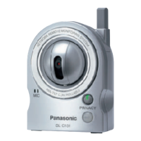
4.1.8. I/O Terminal Block
The system of the Input terminal is connected to the Input Port of the IC101 GPIO.
Due to Internal Pull-up Resistance, the PNP Transistor (Q905,Q904) on the following level is usually in the OFF state and the Input
Port connected to the collector is at L level.
If the terminal is short-circuited with the GND, or the signal of L level is input, the PNP Transistor goes ON and the Input Port goes
to H level.
The CPU checks the state of this port regularly to detect a change in this signal.
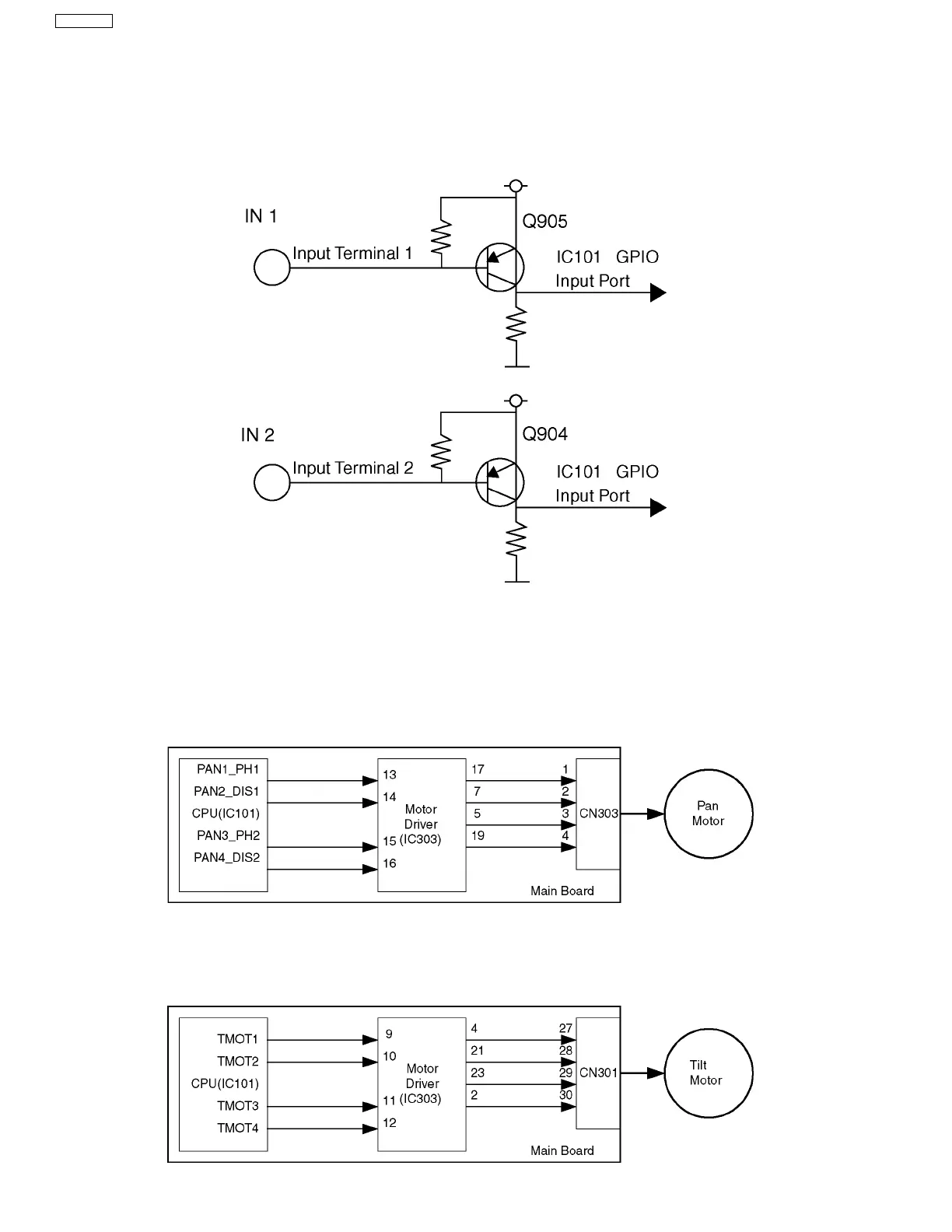
4.1.9. PAN Control Block
A pan motor is initiated when CPU (IC101) on a Main Board controls the Motor Driver IC (IC303) on the same board.
A Constant Voltage Bipolar Drive System is employed. The Voltage of Motor Power (VM) is 3.3V. ø15 Stepping Motors are
employed.
DC-DC Converter
Package: 24 pin SOP
4.1.10. TILT Motor Control Block
A Tilt motor is initiated when CPU (IC101) on a main board controls the motor driver IC (IC303) on the same board.
A Constant Voltage Bipolar Drive System is employed. The Voltage of Motor Power (VM) is 3.3V.
ø15 Stepping Motors are
employed.