63
12.3.6 Remote Controller Mounting, Installation and Connection
12.3.7 How to Take Out Front Grille
Please follow the steps below to take out front grille if necessary such as when installing or servicing.
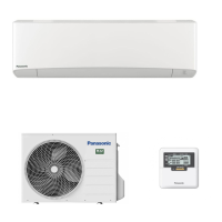
Model Z25***, Z35***, Z42***
1 Pull down 3 caps at the bottom, then remove
3 mounting screws.
2 Cling finger around screw area slot, pull the
bottom plate downward until a click sound
indicates hook is unleashed.
Move the bottom plate forward carefully.
3 Open front panel.
4 Remove 3 mounting screws on the front grille.
5 Slide the 3 lock knobs on the upside of front
grille to unlock position.
6 Set the upper vane to horizontal position.
Set the lower vane to slightly below horizontal
position.
7 Pull the front grille towards you to remove the
front grille.
I
Remote Controller Mounting Location
•
Allow suffi cient space around the remote controller
3
as shown in
the illustration at right.
•
Install in a place which is away from direct sunlight and high humidity.
•
Install in a fl at surface to avoid warping of the remote controller. If
installed to a wall with an uneven surface, damage to the LCD case
or operation problems may result.
•
Install in a place where the LCD can be easily seen for operation.
(Standard height from the fl oor is 1.2 to 1.5 meters.)
•
Avoid installing the remote controller cable near refrigerant pipes or
drain pipes, else it will cause electrical shock or fi re.
I
Remote Controller Installation
•
Remove the remote controller
3
lower case.
(Insert a fl
at-tipped screw driver or similar tool 2 to 3 mm into the gap
at the bottom of the case, and twist to open. Refer to the illustration at
right.) Be careful not to damage the lower case.
•
Do not remove the protective fi
lm which is affi
xed to the upper case
circuit board when remove the remote controller lower case.
•
Secure the lower case to an outlet box or wall. Refer to (A) or (B)
instructions below depending on your choice of cable installation.
•
Be sure to use only the screws provided.
•
Do not over tighten the screws, as it may result in damage to the
lower case.
1. Embed an outlet box (JIS C 8336) into the wall. Outlet box maybe purchased separately. Medium size square outlet box (obtain
locally)
Part No. DS3744 (Panasonic Co., Ltd.) or equivalent.
2. Secure the remote controller lower case to the outlet box with the three accessory screws
4. Make sure that the lower case is fl at against the wall at this time, with no bending.
3. Pass the remote controller cable into the box.
4. Route the remote controller cable inside the lower case through rear feeding-out direction.
5. Insert fi rmly the connector of remote controller cable to connector (CN-RMT) in the upper case circuit board. (Refer to the
illustration at below.)
6. Secure the remote controller upper case to the lower case with the tabs provided.
1. Install the remote controller lower case to the wall with the three accessory screws
5
.
2. Fasten the screws properly until screw head is lower than the rib and reach the base of remote
controller lower case to ensure they do not damage the PCB inside the remote controller 3
.
3. The feeding-out direction for the remote controller cable shall be via the top side.
4. Use nipper to cut a notch at the upper case.
5. Route the remote controller cable inside the upper case. (Refer to the illustration at right).
6. Insert fi rmly the connector of remote controller cable to connector (CN-RMT) in the upper case
circuit board. (Refer to the illustration at right)
7. Secure the remote controller upper case to the lower case with the tabs provided.
Remote controller cable
Remote
controller
3
Remote
controller cable
CAUTION
Install the remote controller cable at least 5 cm away from electric wires
of other appliances to avoid miss-operation (electromagnectic noise).
CAUTION
When the wall is hollow, please be sure to use the sleeve for remote controller cable to prevent dangers caused by mice biting the cable.
Connector
30 mm or more
30 mm
or
more
30 mm
or
more
Remote
controller
lower case
30 mm or more
Remote
controller
3
Lower case
Upper case
A. IF REMOTE CONTROLLER CABLE IS EMBEDDED
B. IF REMOTE CONTROLLER CABLE IS EXPOSED
Upper case
Screw
driver
Lower case
Gap
Screws
4 or Screws 5
Remote
controller
cable
Notch
Lower case
Lower case
Upper case
Upper
case
Connector
(CN-RMT)
Ta b
Remote controller cable
Remote
controller
lower case
Lower case
Upper case
Upper tab
Connector
(CN-RMT)
Lower tab
Wall
Wall
Rib
Screws 5
Screws
5
Screws
4
Upper case
Lower case
Lower tab
Outlet box (JIS C 8336)
Upper tab
Remote
controller
cable
Connector (CN-RMT)
Wall
Remote controller cable
Rear
feeding-out
position
Lower case
Upper case
Connector (CN-RMT)
Ta b
Lower case
Upper case
Cap and Screw
(3 location)
Bottom
plate
2
1
Front
panel
Front grille
Upper vane: Set to horizontal;
Lower vane: Set to slightly below horizontal
LOCK
Lock knob
UNLOCK
Screw
(3 location)
Vane
4
3
7
6
5
 Loading...