

A
Ashley WardSep 5, 2025
What does error F40 mean on a Panasonic KV-S2065L?
- BBethany AdamsSep 5, 2025
If your Panasonic Scanner displays error F40, this indicates a Hopper Drive Error. The suggested solution is to replace the MAIN CONTROL Board.
What does error F40 mean on a Panasonic KV-S2065L?
If your Panasonic Scanner displays error F40, this indicates a Hopper Drive Error. The suggested solution is to replace the MAIN CONTROL Board.
How to troubleshoot the Starting Position Sensor Error on Panasonic Scanner?
To troubleshoot a Starting Position Sensor Error (F51) on your Panasonic scanner, start by removing any dust on the LED on the STARTING POSITION LED Board, or on the light receptor on the STARTING POSITION SENSOR Board. Then, check that the LED on the STARTING POSITION LED Board, the light receptor on the STARTING POSITION SENSOR Board, and the slot location on the carrier board are properly aligned. Inspect the STARTING POSITION LED Board Cable, the RELAY ( LOWER ) Board Cable, the Starting Position Sensor Cable and the RELAY ( UPPER ) Board Cable. If the issue remains, you might need to replace the STARTING POSITION LED Board, the STARTING POSITION SENSOR Board, the RELAY ( LOWER ) Board, the RELAY ( UPPER ) Board, the MOTHER Board, or the MAIN CONTROL Board.
How do I fix an Ending (Front) Position Sensor Error on my Panasonic Scanner?
To resolve an Ending (Front) Position Sensor Error (F55) on your Panasonic scanner, first, remove any dust on the LED on the ENDING (FRONT) LED Board, or on the light receptor on the ENDING (FRONT) SENSOR Board. Also, check that the LED on the ENDING (FRONT) LED Board, the light receptor on the ENDING (FRONT) SENSOR Board and the slot location on the carrier board are properly aligned. Check the ENDING (FRONT) LED Board Cable, the Paper Jam Sensor Cable, the Ending (Front) Sensor Cable and the RELAY ( UPPER ) Board Cable. If the error remains, consider replacing the ENDING (FRONT) LED Board, the PAPER JAM SENSOR Board, the ENDING (FRONT) SENSOR Board, the RELAY ( UPPER ) Board, the MOTHER Board, or the MAIN CONTROL Board.
What is error F20 on a Panasonic KV-S2065L Scanner?
If your Panasonic Scanner displays error F20, it indicates a Shading RAM Error. The suggested solution is to replace the MAIN CONTROL Board.
What does error F34 mean on my Panasonic Scanner?
If your Panasonic Scanner displays error F34, it indicates an EEPROM Error, and you will need to replace the MAIN CONTROL Board.
What causes error F61 on a Panasonic Scanner?
If your Panasonic Scanner displays error F61, it indicates a Front Side Black Level Error. The suggested solution is to replace the MAIN CONTROL Board.
What does error F29 mean on a Panasonic KV-S2065L?
Error F29 on a Panasonic Scanner indicates a Front Gamma RAM Error. Replace the MAIN CONTROL Board to resolve this issue.
What to do if my Panasonic KV-S2065L shows a Paper Jam Sensor Error?
If your Panasonic Scanner displays a Paper Jam Sensor Error (F54), it might be due to dust on the LED of the PAPER JAM LED Board or the light receptor on the PAPER JAM SENSOR Board. Try removing any dust from these components. Also, check that the LED on the PAPER JAM LED Board, the light receptor on the PAPER JAM SENSOR Board, and the slot location on the carrier board are properly aligned. Check the PAPER JAM LED Board Cable, the RELAY ( LOWER ) Board Cable, the Paper Jam Sensor Cable and the RELAY ( UPPER ) Board. You may also need to replace the ENDING (REAR) SENSOR Board Cable or the POINTER Board Cable. If the issue persists, consider replacing the PAPER JAM LED Board, the ENDING (REAR) SENSOR Board, the POINTER Board, the PAPER JAM SENSOR Board, the RELAY ( LOWER ) Board, the RELAY ...
How do I fix a Starting Position Sensor Error on my Panasonic KV-S2065L?
To address a Starting Position Sensor Error on your Panasonic Scanner, begin by removing any dust from the LED on the STARTING POSITION LED Board or the light receptor on the STARTING POSITION SENSOR Board. Make sure that the LED on the STARTING POSITION LED Board, the light receptor on the STARTING POSITION SENSOR Board, and the slot location on the carrier board are properly aligned. Check the STARTING POSITION LED Board Cable, the RELAY (LOWER) Board Cable, and the Starting Position Sensor Cable. If the issue persists, consider replacing the STARTING POSITION LED Board, the STARTING POSITION SENSOR Board, the RELAY (LOWER) Board, the RELAY (UPPER) Board, the MOTHER Board, or the MAIN CONTROL Board.
What should I do if my Panasonic Scanner has a Back Side Lamp Lighting Error?
If your Panasonic scanner displays a Back Side Lamp Lighting Error (F69), start by checking the CIS ( B ) Cable and the CIS ( B ) LED Cable. If the problem continues, you may need to replace the Back Side Image Sensor, the DRIVE Board, the MOTHER Board, or the MAIN CONTROL Board.
Specifies the minimum and recommended CPU for scanner operation.
Details the required RAM capacity for the scanner.
Lists compatible operating systems for the scanner.
Recommends specific SCSI boards for optimal performance.
Outlines FCC compliance rules and warnings for digital devices.
Provides essential safety instructions regarding fire and electric shock hazards.
Covers handling, liquids, items on unit, environment, surface, and carrying.
Includes power cord, disassembly, and warranty voiding.
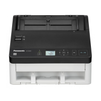
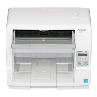
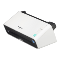
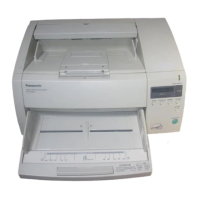
Identifies and labels external parts of the scanner unit.
Labels the display panel, power switch, and indicator lights.
Explains the function of each key and the LCD display on the control panel.
Guides users on how to select the display language for the scanner.
Details various parameters for customizing scan settings.
Explains how to configure and view scan counters and user settings.
Covers settings for pre- and post-imprinters.
Details miscellaneous settings like buzzer, SCSI ID, and transfer rate.
Demonstrates the step-by-step process of navigating menus and making settings.
Provides detailed explanations for various scan setting options.
Explains the meaning of different messages displayed on the scanner's LCD.
Instructs on separating documents and aligning them in the hopper.
Details how to place documents in the hopper, including capacity limits.
Lists types of documents to avoid and specific handling for fragile papers.
Explains how to choose between front or straight paper paths for scanning.
Details how to set the selector for single or continuous scanning modes.
Explains the use of control sheets for scanning with specific conditions.
Step-by-step guide to remove jammed documents from the main scanning area.
Instructions for clearing paper jams from the document exit path.
Instructions for cleaning the scanner's outer cover and vents.
Details cleaning frequency and specific parts like rollers and sensors.
Provides a detailed procedure for cleaning all rollers using cleaning paper.
Explains how to clean scanning glass, sensor rollers, and document/feed detection sensors.
Step-by-step guide to replace the paper feed roller module.
Detailed instructions for removing and installing the retard roller module.
Advises on using original packing materials and disconnecting cables.
Details steps for folding parts and securing the scanner for transport.
Lists technical details like scanning speed, resolution, and image control.
Details paper handling, weight, interface, and power requirements.
Specifies operating conditions and lists available optional accessories.
Lists common issues like LCD not displaying, double feeding, and jams.
Explains how to resolve specific error codes related to jams and warnings.
Addresses issues related to computer recognition and interface board problems.