7
KX-NS500AG
4 Technical Descriptions
4.1. Block Diagram
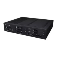
The NS500 series PBX is constructed in Main Unit (NS500) and up to three expansion unit (NS520).
In Main Unit (NS500), CPU Board (MPR) (Master Processor) which controlls whole call of this system is equipped, and, in an
expansion unit, CPU Board (SPR) (Slave Processor) controlling various line interfaces in the unit is equipped with.
Each expansion units are connected to Main Unit with star topology, and time slot exchange function is equipped in Main Unit.
The exclusive interface between basic and expansion units are built with one pair of TDM interface of 8.192MHz, and voice chan-
nel, control channel and addition information channel are secured.
All interface cards except digital extension intefarce (DHLC/DLC) are controlled by CPU Board (MPR)/CPU Board (SPR) directly.
Table.1 Main Unit Card Description
Table.2 Expansion Unit Card Description
Card Description
CPU Board (MPR) Master CPU of NS500 system which controls Main Unit and up to three expansion unit.
Main Unit Mother Board
(LCOT6+MCSLC16+DLC2)
Ext and Trunk combo card which support analog trunk (6ch), analog extension line (16ch) and digital exclusive
line (2ch).
Card Description
CPU Board (SPR) CPU Board (SPR) is a sub CPU card controlling the line card in the expansion unit.
Expansion Unit Mother Board
(MCSLC16)
Extension line card.
MPR
CortexA8
600MHΈ
Master
FPGA
DPT
I/F
2port
PLD1
Extension
ίEXT_PLDὸ
MCSLC16
S-lab
SLIC/CODEC
x8
LCOT6
DSPG
DE56x3
DSP
RMT
NAND
1GB
SRAM
512KB
EXP-M
DDR3
512MB
Extension
Trunk/DPH
TDM Bus
CPU Bus
IIO SPI
LED(2)/SW(1)/USB Host(1)
Mother Board
CPU
SD Card
PLD2
Trunk
ίCO_PLDὸ
Fig.1 Block Diagram
Main Unit
 Loading...