Pin No. Pin Name I/O Description
92 WE3/DQMUU/ICIOW
R/PTK[7]
O/I/O D31-D24 select signal/DOM (SDRAM) /PCMCIA I/O write/I/O port K
93 RD/WR O Read/Write
94 AUDSYNC/PTE[7] O/I/O AUD synchronization/I/O port E
95 VssQ - Power for I/O (0V)
96 CS0/MCS[0] O Chip select 0/mask ROM chip select 0
97 VccQ - Power for I/O (3.3V)
98 CS2/PTK[0] O/I/O Chip select 2/I/O port K
99 CS3/PTK[1] O/I/O Chip select 3/I/O port K
100 CS4/PTK[2] O/I/O Chip select 4/I/O port K
101 CS5/PTK[3] O/I/O Chip select 5/CE1 (Area 5PCMCIA)/I/O port K
102 CS6/CE1B O Chip select 6/CE1 (Area 6PCMCIA)
103 CE2A/PTE[4] O/I/O CE2(Area 5PCMCIA)/ I/O port K
104 CE2B/PTE[5] O/I/O CE2(Area 6PCMCIA)/ I/O port K
105 CKE/PTK[5] O/I/O CK Enable (SDRAM) / I/O port K
106 RAS3L/PTJ[0] O/I/O RAS for low 32M/64M bytes address (SDRAM) /I/O port J
107 PTJ[1] I/O I/O port J
108 CASL/PTJ[2] O/I/O RAS for low 32M/64M bytes address (SDRAM) /I/O port J
109 VssQ - Power for I/O (0V)
110 CASU/PTJ[3] O/I/O RAS for low 32M bytes address (SDRAM) /I/O port J
111 VssQ - Power for I/O (3.3V)
112 PTJ[4] I/O I/O port J
113 PTJ[5] I/O I/O port J
114 DACK0/PTD[5] O/I/O DMA acknowledge0/I/O port D
115 DACK1/PTD[7] O/I/O DMA acknowledge1/I/O port D
116 PTE[6} I/O I/O port E
117 PTE[3} I/O I/O port E
118 RAS3U/PTE[2] O/I/O RAS for low 32M bytes address (SDRAM) / I/O port E
119 PTE[1] I/O I/O port E
120 TDO/PTE[0] O/I/O Test data output/I/O port E
121 BACK O Bus acknowledge
122 BREQ I Bus request
123 WAIT I Hardware wait request
124 RESETM I Manual reset request
125 ADTRG/PTH[2] I Analog trigger/input port H
126 IOIS16/PTG[7] I IOIS168 (PCMCI) / I/O port G
127 ASEMD0/PTG[6] I ASE mode:4/I/O port G
128 ASEBRKAK/PTG[5] I/O ASE break acknowledge/I/O port G
129 PTG[4]/CKIO2 I/O Input port G/clock output
130 AUDATA[3]/PTG[3] I/O/I AUD data/input port G
131 AUDATA[2]/PTG[2] I/O/I AUD data/input port G
132 Vss - Power supply (0V)
- Vss - Power supply (0V)
133 AUDATA[1]/PTG[1] I/O/I AUD data/input port G
134 Vcc - Power supply (*3)
- Vcc - Power supply (*3)
135 AUDATA[0]/PTG[0] I/O/I AUD data/input port G
136 TRST/PTF[7]/PINT[15] I Test reset/input port F/port interruption
137 TMS/PTF[6]/PINT[14] I Test mode switch/input port F/port interruption
138 TDI/PTF[5]/PINT[13] I Test mode switch/input port F/port interruption
139 TCK/PTF[4]/PINT[12] I Test clock/input port F/port interruption
140 IRS3/PTF[3]/PINT[11] I External interrupt request/input port F/port interruption
141 IRS2/PTF[2]/PINT[10] I External interrupt request/input port F/port interruption
142 IRS1/PTF[1]/PINT[9] I External interrupt request/input port F/port interruption
143 IRS0/PTF[0]/PINT[8] I External interrupt request/input port F/port interruption
144 MD0 I Clock mode setting
145 Vcc-PLL1*2 - Power for PLL1 (*3)
146 CAP1 - External capacity terminal for PLL1
147 Vss-PLL1*2 - Power for PLL1 (0V)
148 Vss-PLL2*2 - Power for PLL1 (1V)
149 CAP2 - External capacity terminal for PLL2
150 Vcc-PLL2*2 - Power for PLL2 (*3)
151 AUDCK/PTH[6] I AUD clock/input port H
152 Vss - Power supply (0V)
153 Vss - Power supply (0V)
- Vss - Power supply (0V)
154 Vcc - Power supply (*3)
66
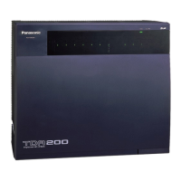
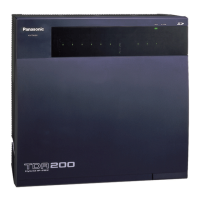
KX-TDA200BX
 Loading...

