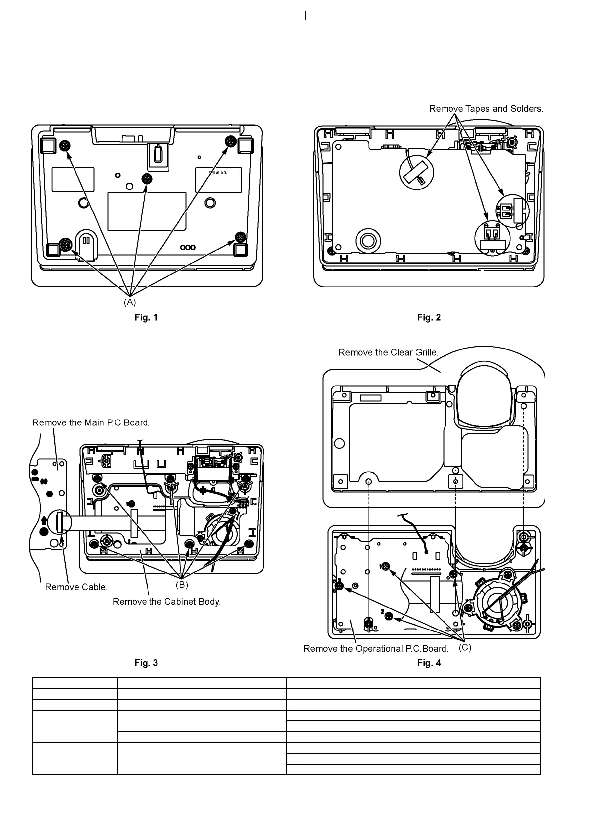
5 DISASSEMBLY INSTRUCTIONS
5.1. Base Unit
Shown in Fig.- To Remove Remove
1 Cabinet Cover Screws (2.6 × 14)........(A) × 5
2 Main P.C.Board Tapes and Solders
3 Main P.C.Board Cable
Main P.C.Board
Cabinet Body Screws (2.6 × 14)..........(B) × 6
4 Operational P.C.Board Clear Grille
Screws (2.6 × 8).............(C) × 4
Operational P.C.Board
14
KX-TG1283JXS / KX-TG1283JXT / KX-TCA122CXS / KX-TCA122CXT / KX-TCA121CXS / KX-TCA121CXT
 Loading...