12
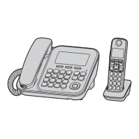
KX-TG2873BXS/KX-TGA280BXS
4.3.5. Telephone Line Interface
Telephone Line Interface Circuit:
Function
• Ring signal detection
• Clip signal detection
• ON/OFF hook circuit
• Pulse dial circuit
• Side tone circuit
Ring signal detection:
In the standby mode, Q105 is open to cut the DC loop current and decrease the ring load. When ring voltage appears at the T (A)
and R (B) leads (When the telephone rings), the AC ring voltage is transferred as follows:
A → L101 → IC100 Pin 1
B → L101 → C106 → R109 → IC100 Pin 8
Ring signal from T-R is input to Ringer IC100 and output from pin 5 of IC100. Then it is detected through the following route.
IC100 5pin → R119 → PC100 → IC4 Pin 63 (BELL)
Clip (:Calling Line Identification presentation: Caller ID) signal detection:
The Clip signal voltage is transferred as follows;
A → L101 → C900 → R904 → C904 → R914 →IC4 Pin 107 (CIDin+)
B → L101 → C901 → R905 → C905 → R913 →IC4 Pin 112 (CIDin-)
ON/OFF HOOK Circuit:
Q104 is turned ON when IC4 detects the Ring signal, the handset of base unit is off-hook or the TALK key of the handset is
pressed. This causes Q105 to be turned ON and the line will be closed. (The Line Loop state).
A → L101 → D102 (3→1) → Q105 → Q109 → R126 → R179 → Q107 → D102 (4→2)→ L101 → B [Line Loop]
Pulse Dial Circuit:
Pin 94 of DSP IC4 (HOOK/DP) turns Q104 ON/OFF to make the pulse dialing.
Side Tone Circuit:
Basically this circuit prevents the TX signal from feeding back to RX signal. As for this unit, TX signal feed back from Q109 is
canceled by the canceller circuit of DSP (IC4).

 Loading...