Mini VRF SYSTEM
Remote Controller Functions
5 - 29
3. Remote Controller Servicing Functions
5
<Procedure of CZ-RTC5B>
(1) Keep pressing the
, and
buttons simultaneously for 4 or more seconds.
The “Maintenance func” screen appears on the
LCD display.
(2)
Press the or button to see each
menu.
If you wish to see the next screen instantly, press
the or button.
Select “5. Sensor info.” on the LCD display and
press the button.
Select the “Unit no.” by pressing the or
button for changes.
Then press the button.
Display sensor information of the unit.
See the information by pressing the or
button.
SM830231-00_Single_欧州.indb 21 2014/04/04 13:48:35
Sensor info.
Unit no. Code no. Data
Scroll
20:30 (THU)
01
02
00
0028
0026
0026
1-1
Maintenance func
1. Outdoor unit error data
2. Service contact
3. RC setting mode
4. Test run
Sel. Page [ ] Confirm
20:30 (THU)
Maintenance func
5. Sensor info.
6. Servicing check
8. Detailed settings
Sel. Page [ ] Confirm
20:30 (THU)
7. Simple settings
Sensor info.
Unit no. Code no. Data
Sel. Next
20:30 (THU)
01
02
00
0028
0026
0026
1-1
Sensor info.
Unit no. Code no. Data
Scroll
20:30 (THU)
01
02
00
0028
0026
0026
1-1
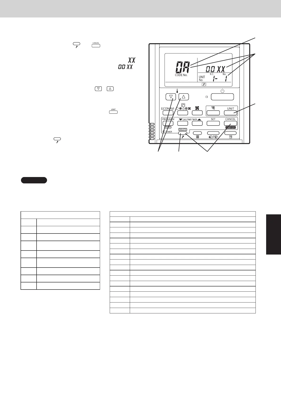
<Procedure of CZ-RTC4>
(1)
Press and hold the and buttons
simultaneously for 4 seconds or longer.
(2)
The unit No. “X-X” (main unit No.), item code “
”
(sensor address), and servicing monitor “ ”
(sensor temperature) are displayed on the remote
controller LCD display.
(3)
Press the temperature setting /
and select the item code to the address of the
buttons
sensor to monitor.
(4)
If group control is in effect, press the
to select the unit to monitor.
button
Press the temperature setting buttons to select the
item code to change.
(5)
Press the button to return to normal remote
controller display.
NOTE
The temperature display appears as “- - - -” for unit that are not connected.
* If monitor mode is engaged while normal operation is in progress, only the parts of the LCD display shown in the
figure will change. Other parts continue to display the same information as during normal operation.
* Display shows a discharge temperature of
00XX at unit No. 1-1.
A
°
°
(3) (4)
(3)
(4)
(1)
(2)
(5)
(4)
Indoor unit sensors
00 Room temp. controlled*
01 Remote controller temp.
02 Indoor unit intake temp. (TA)
03
Indoor unit heat exchanger
temp. E1 (E1)
04 —
05
Indoor unit heat exchanger
temp. E3 (E3)
06 Discharge air temp. (BL)
07 Discharge air temp. setting
08 Indoor unit MOV pulse (MOV)
Outdoor unit sensors
Unit No.1
0A Discharge temp. (DISCH)
0C High-pressure sensor temp.
0D Heat exchanger gas (EXG)
0E Heat exchanger liquid (EXL)
11 Outdoor air temp. (TO)
12 Inverter secondary current
13 Inverter primary current (L2 phase) (Three phase only)
15 MOV pulse 1 (MOV1)
19 Inverter actual operating frequency
1A Sub cooler (MOV4)
1B Inverter primary current (L1 phase)
1D Low-pressure sensor temp.
1E Suction temp. (SCT)
21 Inverter primary current (L3 phase) (Three phase only)
24 Temp. sensor at refrigerant gas outlet of dual-tube temp. (SCG)
26 High-pressure
27 Low-pressure
*Room temp. controlled: = Controlled room temperature
•When body thermostat controlled:
Controlled room temperature = Indoor unit intake temp. (TA) – Intake temperature shift (*1)
•Remote control thermostat controlled:
Controlled room temperature = Remote controller temp.
*1 Intake temperature shift: This is the shift value considered the temperature difference between the upper area
and lower area of the room in heating mode.
It is the value of the code “06” in the indoor unit’s EEPROM setting.
Cooling mode: = 0
SM830289-01_欧州向け R32 mini VRF 8,10HP SM&TRSM.indb 29SM830289-01_欧州向け R32 mini VRF 8,10HP SM&TRSM.indb 29 2021/05/07 10:16:232021/05/07 10:16:23
 Loading...


