4. Outdoor Unit Fan Control
2WAY VRF SYSTEM
Control Functions
4. Special Control
(4) Crankcase Heater Control [CH]
When the compressor stops, the crankcase heater is turned ON / OFF.
Internal Calculated
3-1. Type of Electronic control valves
3-2. Power Initialization
MOV1 is for adjusting refrigerant flow amount of outdoor heat exchanger.
MOV4 is for adjusting refrigerant flow amount of Sub cooler.
If no indoor units have started (even once) after the power supply to the outdoor unit, the MOV holds the fully
open.
3-3. Control of Electronic control valves
Electronic control valves for heat exchanger control according to the operation mode.
Cooling HeatingMode of system
Compressor
MOV1 (pulse)
Stop
Stop
0
Operation
Full open
Stop
0*
1
Operation
0 ~ Full*
3
Stop
0
MOV4 (pulse) 00 ~ Full00 ~ Full0*
2
*When the indoor unit receives the signal for operation request from the control equipment, the pulse turns
other than the fully open (regardless of the thermostat ON/OFF or operating ON/OFF).
It is necessary to switch ON the power supply again if the fully open are required.
*1 However, 100 pulses remain for 2 minutes after unit stopped.
*2 When the outdoor unit stops and low pressure ≤ 0.16 MPa, 60 pulses remain for 30 seconds.
*3 If any one compressor in the outdoor unit is operating in heating mode, electronic control valves perform SH
control.
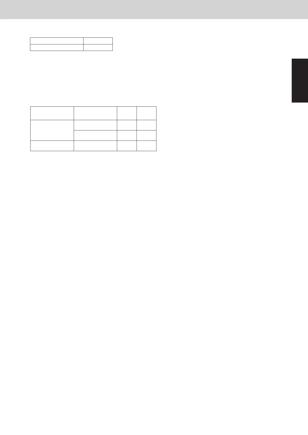
(3) Electronic Control Valves [MOV1, MOV4]
Fully open
MOV1
MOV4
Pulse
3000
480
The fan rotating numbers will be changed according to the fan steps.
These outdoor units utilize a DC fan motor that can be controlled in a maximum of 14 steps.