Mini VRF SYSTEM
Test Run
7 - 2
7
1. Preparing for Test Run
1. Preparing for Test Run
Before attempting to start the air conditioner, check the following.
(1) All loose matter is removed from the cabinet
especially steel filings, bits of wire, and clips.
(2) The control wiring is correctly connected and all
electrical connections are tight.
(3) The protective spacers for the compressor used
for transportation have been removed. If not,
remove them now.
(4) The transportation pads for the indoor fan have
been removed. If not, remove them now.
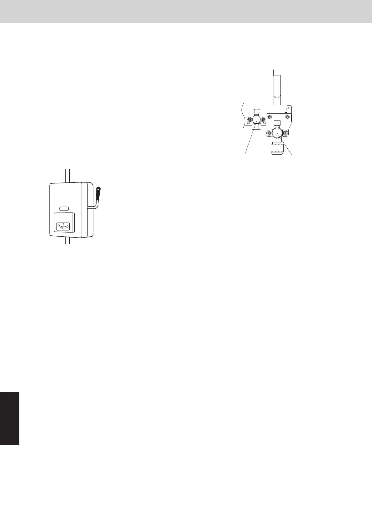
(5) The power has been connected to the unit for at
least 5 hours before starting the compressor. The
bottom of the compressor should be warm to the
touch and the crankcase heater around the feet of
the compressor should be hot to the touch.
ON
(Power must be turned
ON at least 5 hours before
attempting test run)
Power mains switch
(6) Both the gas and liquid tube service valves are
open. If not, open them now.
(7) Request that the customer be present for the
test run. Explain the contents of the operating
instructions, then have the customer actually
operate the system.
(8) Be sure to give the operating instructions and
installation instructions to the customer.
(9) When replacing the outdoor unit control PCB, be
sure to make all the same settings on the new
outdoor unit control PCB as were in use before
replacement.
The existing EEPROM is not changed, and is
connected to the new outdoor unit control PCB.
Gas tube
Liquid tube
2. Test Run Procedure
*
Note:
These settings are not made on the indoor unit
control PCB.
Recheck before the test run.
System address setting
Set the remote controller to a
test run.
Return remote controller
to normal mode.
Follow “7. Self-Diagnosis Function Table and
Contents of Alarm Display” and resolve the
problem.
Test run preparation is completed.
(Do not allow short-circuited pin to remain short-circuited.)
Make necessary
corrections.
Make necessary
corrections.
Check alarm
contents.
Check alarm
contents.
indoor and outdoor
units.
Turn off power to
to indoor and
Turn off power
outdoor units.
Short circuit the A.ADD pin on
outdoor unit control PCB (Main)
for over 1 second long and then
open circuit.
Short circuit the A.ADD pin on outdoor
unit control PCB (Main) for over 1 second
long and then open circuit.
Turn on power to indoor and
outdoor units only for that
refrigerant system.
LEDs 1 and 2 blink alternately.
(Approx. 2 - 3 minutes)
Disconnect link wires for multiple
refrigerant system.
LEDs 1 and 2 blink alternately.
(Approx. 2 - 3 minutes)
Set the number of indoor units.
CASE 1
CASE 2
Are LEDs 1 and 2 on outdoor unit
control PCB OFF?
Connect link wires to original place.
Are LEDs 1 and 2 on outdoor unit
control PCB OFF?
Does system operate?
If the terminating resistance pin on outdoor unit control PCB (Main) is
made link wiring more than 2 refrigerant systems, set to OPEN side
excepting the nearest outdoor unit and the farthest outdoor unit from
the central controller.
Are indoor and outdoor control wires
connected to a multiple refrigerant system?
Is it possible to turn on power only for
1 refrigerant system where the test run will be
performed?
NO
YES
YES
YES
End test run.
NO
NO
YES
NO
*
<Outdoor unit control PCB (Main)>
Number of indoor units
setting switch
(SW3 and SW4)
<Outdoor unit control PCB (Main)>
System address setting
switch
(SW1 and SW2)
See “5. Test Run
Using the Remote
Controller”.
YES
NO
(Check link wiring.)
* See “7. Self-Diagnosis Function Table and
Contents of Alarm Display”.
SM830289-01_欧州向け R32 mini VRF 8,10HP SM&TRSM.indb 2SM830289-01_欧州向け R32 mini VRF 8,10HP SM&TRSM.indb 2 2021/05/07 10:16:432021/05/07 10:16:43