Mini VRF SYSTEM
Test Run
7 - 8
7
4. Auto Address Setting
1-1 1-2 1-3 1-10
(SW2)
(SW1)
12
ON
(SW4)
0
(SW3)
1
ON
Case 1
Auto Address Control from Outdoor Unit
1. Check the refrigerant system’s Address Setting Rotary switch (SW2) on outdoor unit control PCB (Main) to “1”
and the Dip switch (SW1) to “0” (at shipment).
ON
OFF
21
2. Regarding the setting of the number of indoor units connected to the outdoor unit, set the Dip switch (SW3) for
setting the number of indoor units on outdoor unit control PCB (Main) connected to the outdoor unit to “1”
1
ON
ON
OFF
and set the Rotary switch (SW4) to “0”.
3. Turn on power to indoor and outdoor units.
4. Short circuit the A.ADD pin on outdoor unit control PCB (Main) for over 1 second long and open circuit.
Communication for auto address setting begins.
* To cancel, short circuit the A.ADD pin again for over 1 second long and then open circuit. The
LED that indicates auto address setting goes out and the process is stopped.
Be sure to perform auto address setting again.
Auto address setting is completed when LEDs 1 and 2 on outdoor unit control PCB (Main) go out.
5. Remote control operation is now available.
* When auto address setting is controlled by the remote controller, perform auto address setting by the remote
controller after step 3 described above.
4. Auto Address Setting
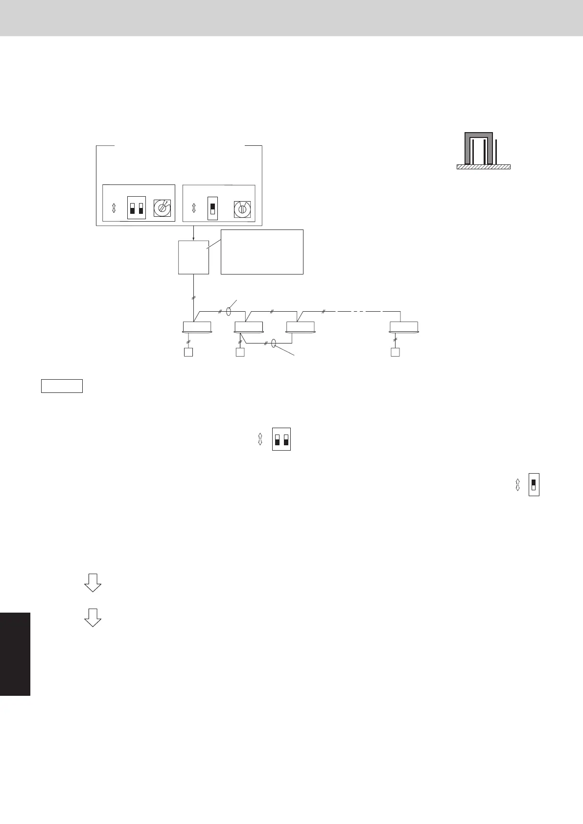
Example: Basic Wiring Diagram (1)
• Case of no link wiring
(Inter-unit control wiring is not connected to a multiple system.)
Indoor unit address setting is possible without starting the compressor.
Unit 1 setting (outdoor main unit)
Number of indoor
units
(10 units setting)
System address
(System 1 setting)
Remote control wiring
for group control
Inter-unit control wiring
Outdoor Unit
Indoor unit
Remote controller
Set the terminating
resistance pin to
SHORT side.
(CN-TERMINAL)
Unit 1
(Main)
* It is not necessary to control the
terminating resistance pin (3P)
(CN-TERMINAL) on the outdoor
unit control PCB.
3P pin is plugged in SHORT side
at shipment. Conrm it is plugged
in SHORT side.
3P terminating
resistance pin
(SHORT side)
OPENSHORT
1-1 1-2 1-3 1-9
(SW2)
(SW1)
12
ON
(SW4)
9
(SW3)
1
ON
ON
ON
OFF
OFF
Setting of terminal pin (CN-TERMINAL)
Refrigerant circuit No. 1
Unit No. 1 (Main) : short-circuit (at shipment)
Refrigerant circuit No. 2 to Z-1
Unit No. 1 (Main) : open-circuit
Refrigerant circuit No. Z
Unit No. 1 (Main) : short-circuit (at shipment)
Unit No. 2 (Sub) : short-circuit (at shipment)
Example: Basic Wiring Diagram (2)
• Case of link wiring
No. 1 refrigerant system
* See “ATTENTION!”.
1-1 1-2 1-131-3
2-1 2-
-9
(SW2)
(SW1)
12
ON
(SW4)
9
(SW3)
1
ON
(SW2)
2
(SW1)
12
ON
(SW4)
3
(SW3)
1
ON
No. 2 refrigerant system
No. Z refrigerant system
Unit 1 setting (outdoor main unit)
System address
(System 1 setting)
Number of indoor
units
(13 units setting)
Unit 1
(Main)
Set the terminating
resistance pin to
SHORT side.
(CN-TERMINAL)
Remote control wiring for
group control
Outdoor unit
system 1
Inter-unit
control wiring
Inter-unit
control wiring
(2WAY VRF)
Remote
Controller
Indoor
unit
Inter-unit control wiring
Central Controller
Unit 1 setting (outdoor main unit)
System address
(System 2 setting)
Number of indoor
units
(9 units setting)
Unit 2
(Sub)
Unit 1
(Main)
Unit 1
(Main)
Set the terminating
resistance pin to
OPEN side.
(CN-TERMINAL)
Set the terminating
resistance pin to
SHORT side.
(CN-TERMINAL)
Outdoor unit
system 2
Outdoor unit
system Z
Inter-outdoor unit control wiring
To Z refrigerant system indoor unit
Inter-unit control wiring
Inter-unit control wiring
Remote control wiring for
group control
Remote Controller
Indoor unit
ON
ON
ON
ON
OFF
OFF
OFF
OFF
SM830289-01_欧州向け R32 mini VRF 8,10HP SM&TRSM.indb 8SM830289-01_欧州向け R32 mini VRF 8,10HP SM&TRSM.indb 8 2021/05/07 10:16:462021/05/07 10:16:46