3 - 22
Mini VRF SYSTEM
Outdoor Unit Repair Procedures
3
8. Compressor
2WAY SYSTEM
Outdoor Unit Repair Procedures
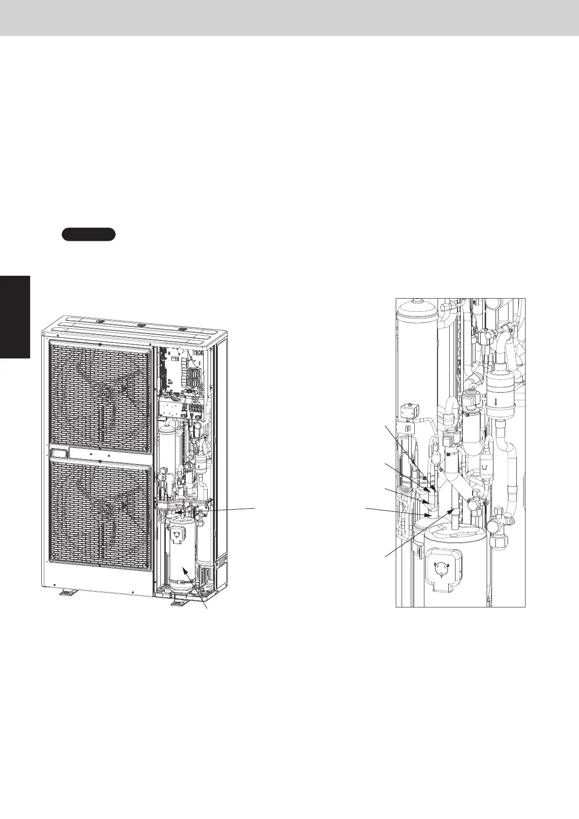
9. Compressor
8-3. Removing Compressors
Use caution to prevent water or foreign particles from invading the refrigerant tube while removing and installing
the compressor.
8-3-1. Removing Compressors
(1)
(2)
(3)
(4)
(5)
(6)
(7)
(8)
(9)
After recovering refrigerant in the system, replace the nitrogen gas through the service valve port.
Remove the insulator containing the compressor and heat insulating material surrounding the oil balance tube.
Remove the compressor terminal cap and then take out the supply terminal.
Remove the crankcase heater.
Remove the hexagonal nuts with washer from three locations.
Cut out the tube on the compressor side because the suction tube showing in the figure is rigid and unmovable.
Remove each welded part on the discharge side (one location) and on the oil balance tube (one location) showing
in the figure.
Protect the sensor part, sheet-metal area, lubber, lead wire, clamper, etc.
Pull the compressor toward you.
Remove the welded part on the suction side of the cut-out tube of the compressor side attached to the suction tube.
SM830233-01_2WAY SYS.indb 33 15/03/05 18:25:18
NOTE
Discharge side welded part
(one location)
Oil balance tube welded part
(one location)
Suction tube
Suction side welded part
Compressor
Tube of compressor side
SM830289-01_欧州向け R32 mini VRF 8,10HP SM&TRSM.indb 22SM830289-01_欧州向け R32 mini VRF 8,10HP SM&TRSM.indb 22 2021/05/07 10:12:232021/05/07 10:12:23