6 - 3
1. Contents of Remote Controller
Switch Alarm Display
Mini VRF SYSTEM
Trouble Diagnosis
6
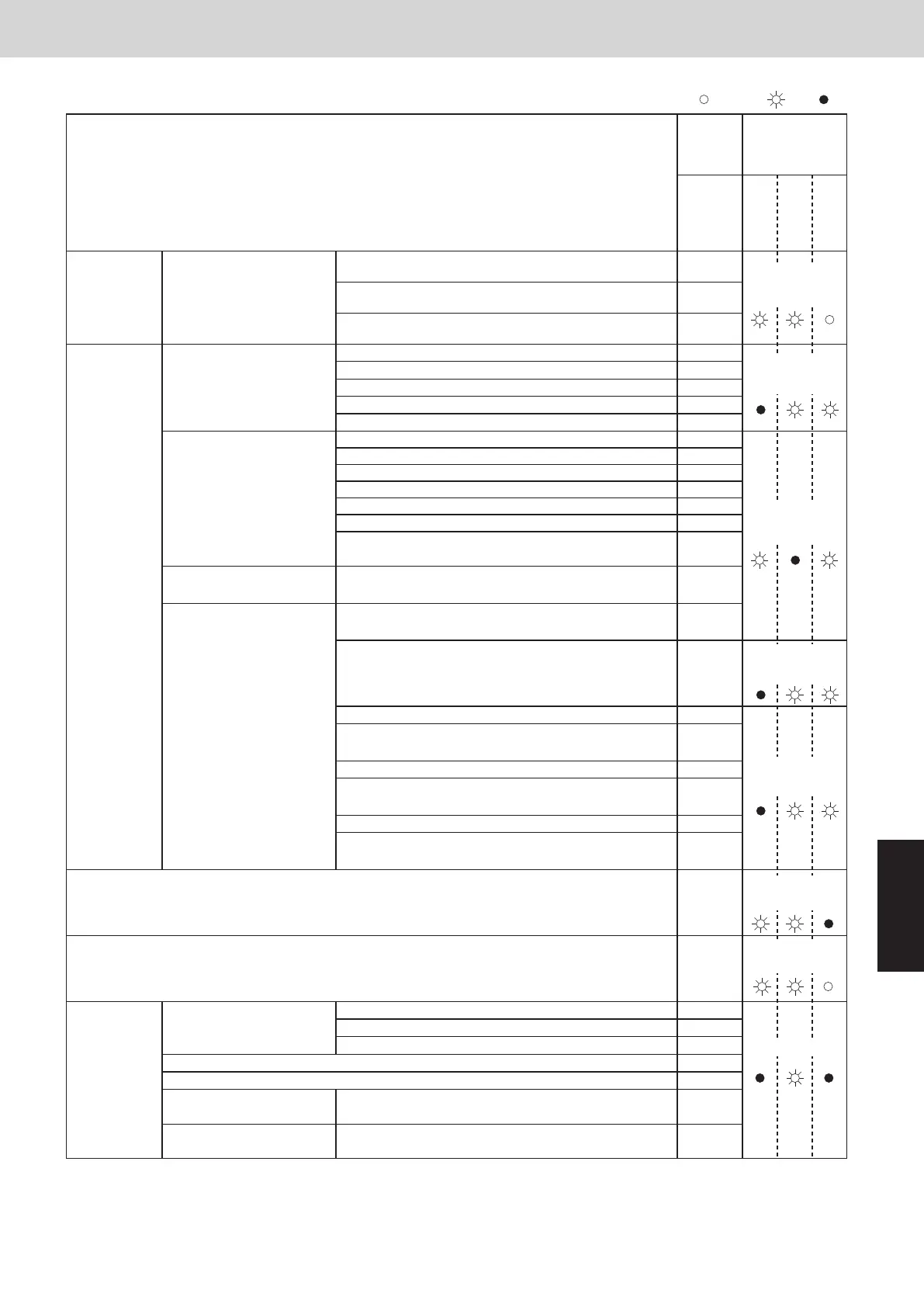
1.Contents of Remote Controller
Switch Alarm Display
2WAY SYSTEM
Trouble Diagnosis
ON: Blinking: OFF:
Possible cause of malfunction
Wired
remote
control
display
Wireless
remote controller
receiver display
Operation
Timer
Standby
for heating
Serial
communication
errors
Miss-setting
Remote controller is detecting
error signal from indoor unit.
Error in receiving serial communication signal. (Signal from
main indoor unit in case of group control) Outdoor system
address, indoor unit address, or indoor unit address
independent/main/sub unit setting has not been made.
(Auto address is not completed.)
Error in transmitting serial communication signal.
Indoor unit is detecting error signal from remote controller and system controller.
Indoor unit is detecting error
signal from outdoor unit.
Error in receiving serial communication signal.
When turning on the power supply, the number of
connected indoor units does not correspond to the number
set. (Except R.C. address is “0.”)
Group wiring failure of indoor units in the refrigerant system
(occurring when remote controller is operated immediately
after auto address setting)
•
•
•
<E01>
<E02>
<<E03>>
<<E09>>
<<L09>>
F06
F07
F08
E04
E08
<E06>
Outdoor unit is detecting error
signal from indoor unit.
Error in receiving serial communication signal.
There is an indoor unit which does not send signals when
the power is ON.
•
•
Indoor unit address setting is duplicated.•
Duplicated remote controller “main” setting.•
Auto address setting start is prohibited.
AP pin was short-circuited at time when auto address setting
was started.
Indoor unit communication
error of group control wiring.
Error of main indoor unit in receiving serial communication
signal from sub indoor units.
During auto. address setting,
number of connected units
does not correspond to
number set.
Improper setting
Improper setting
Improper setting
Indoor unit
Number of connected indoor units is less than the number set.
Number of connected indoor units is more than the number set.
No indoor unit is connected during auto. address setting.
Main outdoor unit is detecting error signal from sub outdoor unit.
Duplicated outdoor unit address.
Error of sub outdoor unit in receiving serial communication
signal from main outdoor unit.
Outdoor unit serial communications failure.
Connected indoor unit is not a multi unit.
Duplication of main indoor unit address setting in group control.
Duplicated indoor unit priority (priority indoor unit).
Duplicated indoor unit priority (non-priority indoor unit) and
outdoor unit.
Indoor unit address is not set.
Capacity code of indoor unit is not set.
4-way valve operation failure
Duplication of outdoor R.C. address setting.
Capacity code of outdoor unit is not set.
Group control wiring is connected to individual control indoor unit.
E12
E18
E16
E20
E15
E24
E25
E29
E30
<L03>
L06
L08
L05
<<L02>>
L04
L18
L10
L07
Thermistor fault
Outdoor coil gas temp. sensor (EXG)
Outdoor air temp. sensor (TO)
Outdoor coil liquid temp. sensor (EXL)
Continued
Operating lamp
blinking
Heating ready lamp
blinking
Operating lamp
blinking
Heating ready lamp
blinking
Operating and heating
ready lamps blinking
simultaneously
Operating and heating
ready lamps blinking
simultaneously
F04Compressor discharge gas temp. sensor (DISCH)
<<F03>>
<<F10>>
<<F11>>
Indoor coil temp. sensor (E3)
Indoor discharge air temp. sensor (BL)
Indoor suction air (room) temp. sensor (TA)
Operating and
timer lamps blinking
alternately
<<F01>>Indoor coil temp. sensor (E1)
Mismatch in “No. of outdoor units” setting. E26
Thermistor faultOutdoor unit
Operating and timer
lamps blinking
alternately
Indoor unit model does not match with outdoor unit. L13
ON: Blinking: OFF:
Possible cause of malfunction
Wired
remote
control
display
Wireless
remote controller
receiver display
Operation
Timer
Standby
for heating
Thermistor fault Outdoor thermistor is either
open or damaged.
Compressor intake temp. sensor (SCT)
High pressure sensor failure. High pressure trouble.
Improper wiring connections of ceiling panel.
Activation of
protective
device
Protective device in indoor
unit is activated.
Thermal protector in indoor unit fan motor is activated.
Float switch is activated.
Operation of protective function of fan inverter.
Protective device in outdoor
unit is activated.
F12
F16
Low-pressure sensor failure
F17
<<P09>>
<<P12>>
<<P10>>
Faulty drain pump. Drain pump locked.
<<P11>>
<<P01>>
Compressor discharge temperature error.
High pressure switch is activated.
AC power supply has abnormal.
Compressor secondary current is overcurrent.
High load alarm (Forgot to open valves)
Outdoor unit fan motor has failure.
Compressor start failure. Compressor is missing phase or
reverse phase.
When alarm message in other indoor units occurs in case of
group control, unalarmed state of indoor units are inoperative.
Indoor unit communication
error of group control wiring.
P04
P03
P05
P20
P29
<P31>
P22
P16
Operating and timer
lamps blinking
alternately
Timer and heat
ready lamp blinking
alternately
Operating and heat
ready lamp blinking
alternately
< > alarm indication: In some cases may affect the operation of other indoor units.
Abnormal device function
<< >> alarm indication: Does not affect the operation of other indoor units.
EEPROM on indoor unit PCB failure
EEPROM on the main or sub outdoor unit PCB has failed.
Protective
device
for compressor
is activated
Protective device for
compressor is activated.
Operating and timer
lamp blinking
simultaneously
Operating and timer
lamp blinking
simultaneously
Abnormal decrease of low-pressure
Compressor oil sensor
Oil sensor fault.
(Disconnection, etc.)
Timer lamp blinking
Compressor current sensor is disconnected or shorted.
F29
F31
H06
Low oil alarm H07
H08
Compressor HIC has failure. HIC is overcurrent or overheat.
VDC is undervoltage or overvoltage.
H31
H03
Compressor discharge temp. sensor disconnectedH05
H01Compressor primary current is overcurrent.
P14
P08
Timer and heat
ready lamp blinking
alternately
Timer and heat
ready lamp blinking
simultaneously
R32 refrigerant leakage
detection
Refrigerant leakage detection of indoor unit connected with
the remote controller displaying this alarm.
Refrigerant leakage detection of one of the indoor units
connected to the outdoor unit.
R32 refrigerant leakage detection sensor has failure.<<J01>>
Life of refrigerant leak sensor in R32 refrigerant leakage
detection sensor has expired.
<<J02>>
Indoor unit refrigerant leak sensor 1 has failure.(GAS1) <<J03>>
Life of indoor unit refrigerant leak sensor 1 has expired.
(GAS1)
<<J04>>
Indoor unit refrigerant leak sensor 2 has failure.(GAS2) <<J05>>
Life of indoor unit refrigerant leak sensors 1 and 2 has
expired.(GAS1 and GAS2)
<<J06>>
1.Contents of Remote Controller
Switch Alarm Display
2WAY SYSTEM
Trouble Diagnosis
SM830289-00_Sec6.indd 3SM830289-00_Sec6.indd 3 2021/01/29 16:15:402021/01/29 16:15:40