3 - 10
Mini VRF SYSTEM
Outdoor Unit Repair Procedures
3
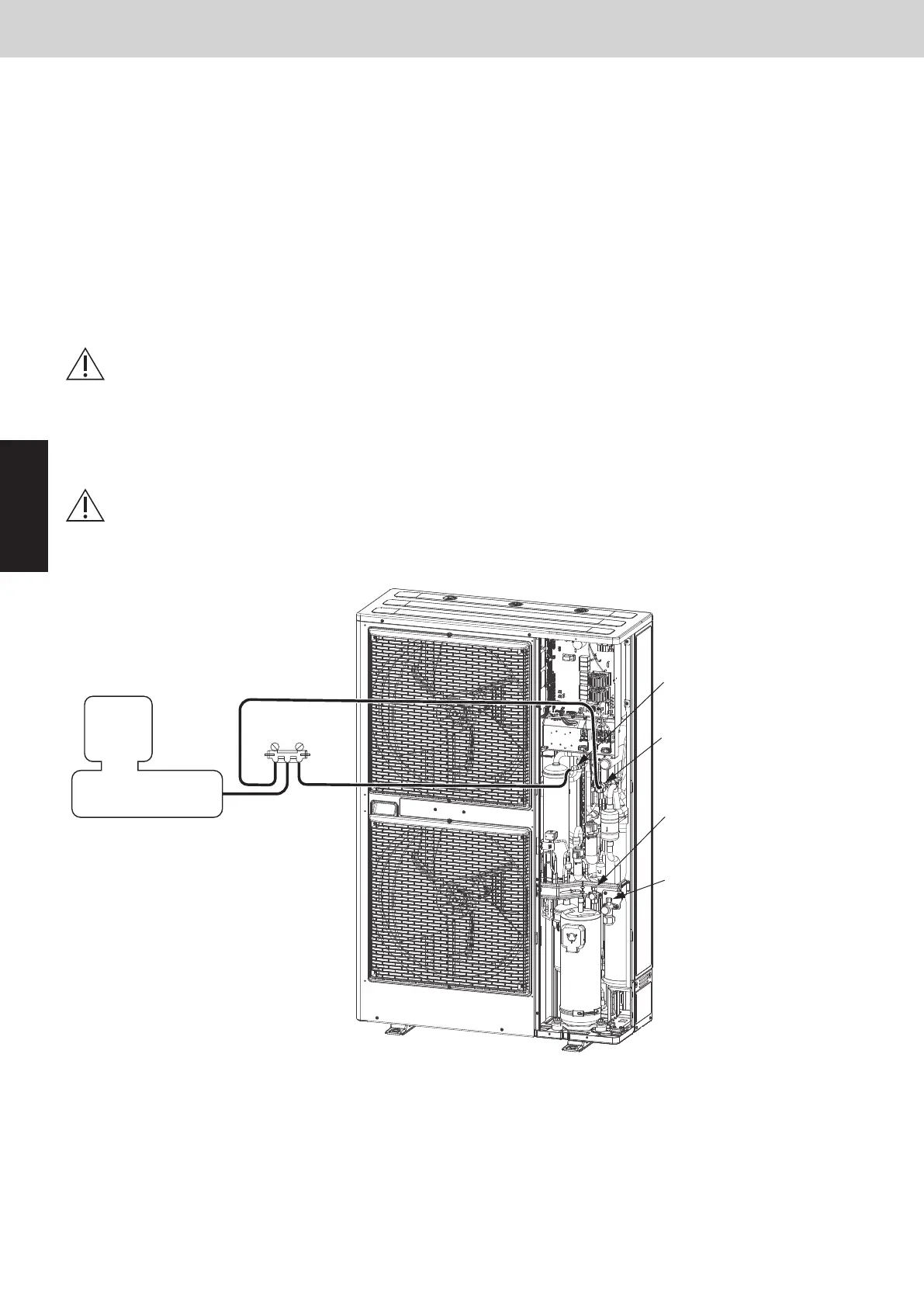
5. Evacuating System
This procedure is carried out to ensure there is no remaining refrigerant or other gases (nitrogen, etc.) in the
repaired outdoor unit and tubing.
5-1. Evacuating Repaired Outdoor Unit
(1) Check that each service valve of the gas tube and liquid tube in the outdoor unit are fully closed.
(2) Connect the manifold gauge valves to the high-pressure and low-pressure sensor outlets of the outdoor unit.
(Fig. 6)
(3) Connect the manifold gauge valves to the vacuum pump.
* If the AP pin on the outdoor control PCB has already been short-circuited, step (4) is not necessary.
(4) Turn off power to the repaired outdoor unit and short-circuit the AP pin on the outdoor control PCB.
By short-circuiting the AP pin and turning on power to the outdoor unit, all electronic
valves in the outdoor unit are forcibly opened and any remaining nitrogen gas can be
recovered. Failure to perform this procedure may result in nitrogen gas remaining in the
refrigerant circuit and causing operating problems. Therefore, never skip this step.
(5) Turn the power ON at the outdoor unit where vacuum will be applied. Then run the vacuum pump and continue
evacuation until the vacuum condition falls to less than –101kPa {–755 mmHg, 5 Torr}.
To ensure proper evacuation, refer to the operating instructions that came with the
vacuum pump.
Fig. 6
Gas tube service port
(for ø7.94mm-dia connector)
High-pressure outlet port
(for ø7.94mm-dia connector)
Low-pressure outlet port
(for ø7.94mm-dia connector)
Liquid tube service port
(for ø7.94mm-dia connector)
Vacuum pump
Manifold gauge
Lo Hi
5-2. Evacuating Refrigerant Tubing Between Indoor and Outdoor Units
For details, refer to the “Installation Instructions” that came with the outdoor unit.
CAUTION
CAUTION
SM830289-01_欧州向け R32 mini VRF 8,10HP SM&TRSM.indb 10SM830289-01_欧州向け R32 mini VRF 8,10HP SM&TRSM.indb 10 2021/05/07 10:11:582021/05/07 10:11:58