3 - 21
Mini VRF SYSTEM
Outdoor Unit Repair Procedures
3
8. Compressor
(16) After evacuating all nitrogen gas from the tubing, apply vacuum to outdoor unit where dry cores were removed
until the pressure is –101kPa {–755 mm Hg, 5 Torr} or less.
(17) Refer to the Installation Instructions for further information. Charge with an amount of refrigerant equal to the
amount that was recovered.
(B) If a ball valve is not installed on the outdoor unit
(1) See Section “3-2-3. Refrigerant recovery procedures (2) : Indoor unit with no ball valve equipped”. Perform
pump down of the refrigerant from all indoor units and inter-unit tubing to the outdoor unit side.
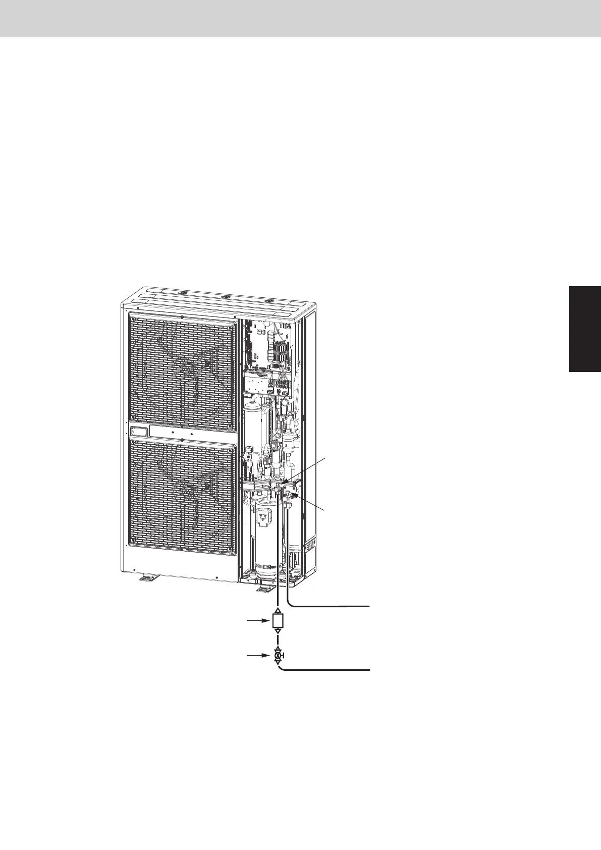
(2) Cut the liquid tube at all outdoor units where dry cores will be attached, then attach the dry cores and ball
valves as shown in Fig. 11.
(3) For the next steps, see the steps (6) – (17) in
(A)
on the previous page.
Fig. 11
Cleaning dry core
Liquid tube service port
(for ø7.94mm-dia connector)
Gas tube service port
(for ø7.94mm-dia connector)
Indoor unit
Dry core (bidirectional:
for R32 refrigerant)
Ball valve
Indoor unit
Gas tube
Liquid tube
SM830289-01_欧州向け R32 mini VRF 8,10HP SM&TRSM.indb 21SM830289-01_欧州向け R32 mini VRF 8,10HP SM&TRSM.indb 21 2021/05/07 10:12:202021/05/07 10:12:20