6 - 20
Mini VRF SYSTEM
Trouble Diagnosis
6
2WAY VRF SYSTEM
Trouble Diagnosis
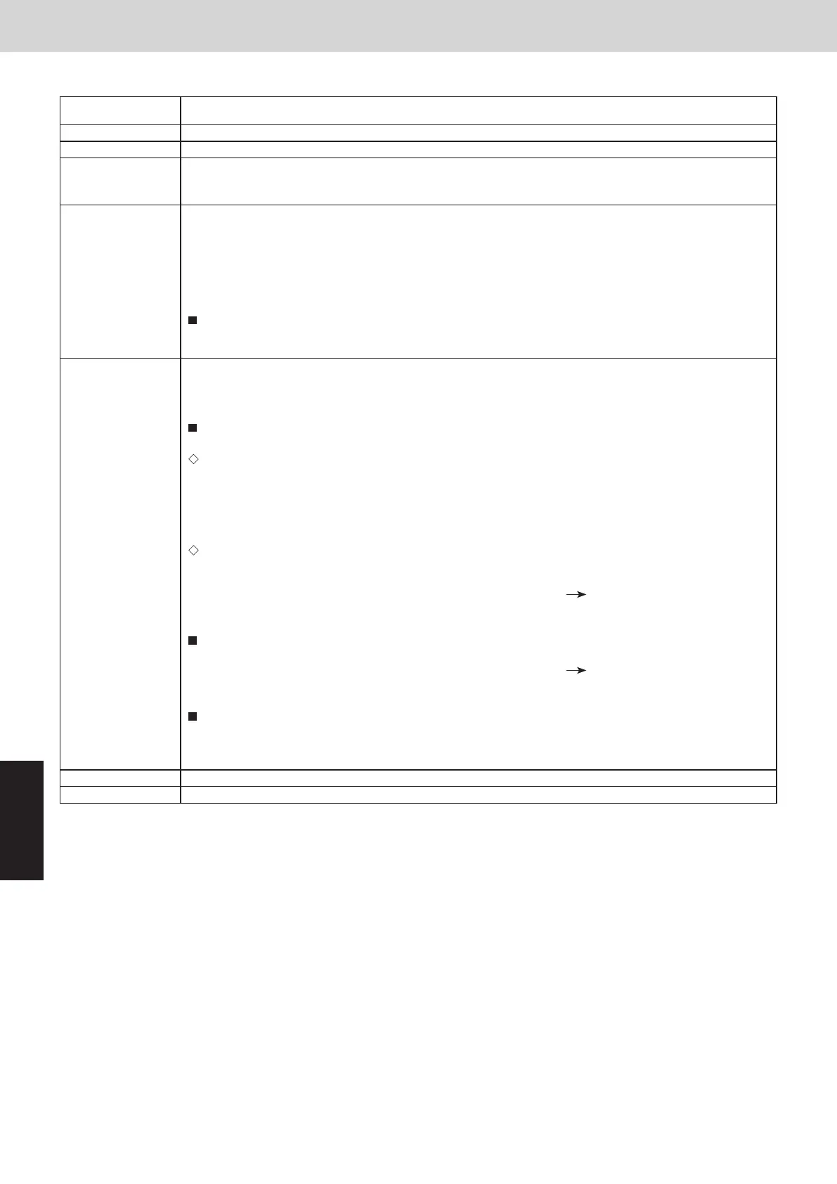
3. 2WAY Alarm Codes
P14 Alarm
Alarm code
Alarm meaning
Alarm conditions
Probable cause
Check and
Correction
Example
Notes
P14
O
2 sensor operation
(1)
1-1 Is an O
2
sensor being used?
System configuration
If “Yes”, see “3-1”.
If “No”, see “2-1”.
If “Yes”, change the setting of item code 0B to “0000”
from “0001”.
If “No”, see “3-1”.
If “Yes”, see “3-3”.
If “No”, see “3-2”.
(2)
2-1 Is the EEPROM setting, item code 0B, on the indoor control board set to 0001?
Indoor EEPROM setting
(3)
3-1 Is the alarm triggered if the EXCT socket (wire) is disconnected, and the power is reset?
Indoor control board
3-2 Since there is no error, see what happens.
3-3 Indoor control board defective
replace board
—
—
(1)
(2)
It is judged an error whenever the outdoor unit receives the signal “O
2 Alarm Generated” from the
indoor unit.
(*) It is judged an error whenever the outdoor unit's EEPROM setting (item code C1) is made at other
than "0". See Section 1.
With the indoor unit's EEPROM setting (item code 0B) set to 0001, the EXCT input was shorted.
—
P16 Alarm
Alarm code
Alarm meaning
Alarm conditions
Probable cause
Check
Correction
Example
Notes
P16
Compressor secondary current is overcurrent.
This alarm occurs when current trouble or current detection trouble occur
(when trouble judgement current is detected in the secondary current).
*
When more than the current values shown in the table are instantly
detected in the secondary current.
Changed to output error by current regardless of the inverter frequency.
(1) Power supply voltage malfunction
(2) Wiring failure (connection failure, miswiring)
* Wiring between HIC PCB and compressor
(1) Check the power supply voltage.
Check whether the voltage between each of the phases is correct while the compressor is running.
(It is necessary to check the compressor while running because the voltage may decrease when the
compressor starts running.)
(2) Check the wiring.
Check whether the following wiring is missing, connection failure or miswiring (position of U, V, W is
properly placed).
・ Wiring between HIC PCB and compressor
・ HIC PCB side
・ Compressor side
(1) Correct the power supply voltage.
(2) Correct the wiring.
(3) Replace the compressor or the HIC PCB.
—
—
Capacity of unit
Secondary current
Current (A)
8HP
24.3
10HP
24.3
SM830237-02_北米向け2WAY_VRF.indb 23 2015/09/08 13:06:28
Inverter compressor
HIC PCB
Secondary
current
P14 Alarm
Alarm code P14
Alarm meaning R32 refrigerant leak detection
Alarm conditions One of the indoor units connected to the outdoor unit has detected R32 refrigerant leak.
Probable cause (1) Connection failure on "Refrigerant tube connection part", or refrigerant leakage caused by crack on "Indoor
unit's inside tube" or "Refrigerant tube between indoor and outdoor units"
(2) Using gases may cause false detection.
Check (1) Identify the indoor unit that detected the refrigerant leak and issues the P08 alarm.
(2) Check "Refrigerant tube connection part", "Indoor unit's inside tube" or "Refrigerant tube between indoor
and outdoor units".
(3) Check if one of the following items is in use that causes false detection.
• Gas appliances with combustible gas (propane, methane)
• Insecticide or hair spray with combustible gas (LPG, etc.)
• Spray contained siloxane, medicines, drugs, lacquer, etc.
If the alarm P08 occurs, the indoor unit fan starts driving in order to prevent refrigerant retention and will
not stop despite pressing the Start/Stop button. In the event of stopping the fan for sake of the investigation
of the causes and repairing the refrigerant leak area, turn o the power after ventilating the room suciently.
Correction (1) Ventilate the room suciently and repair the refrigerant leak area.
(2) Stop using the items that are suspected to cause false detection and remove them with the ventilation
system.
When the refrigerant leak problem is solved, carry out the following procedures.
Replace the present refrigerant sensor with a new one in the following steps. (If the refrigerant sensor
detects the refrigerant leak once, detection performance decreases.)
In the case of R32 refrigerant leakage detection sensor:
• Replace the refrigerant sensor in the refrigerant leakage detection sensor with a new one.
• Reset the refrigerant sensor accumulated energization timer by pressing the switch of R32
refrigerant leakage detection sensor.
As to the procedure for refrigerant sensor replacement and resetting the accumulated energization timer, refer
to the Service Manual of indoor Unit.
In the case of indoor unit with a built-in refrigerant sensor:
• Replace the refrigerant sensor in the indoor unit with a new one.
(The unit with 2 refrigerant sensors must be replaced with both of them.)
• Change Detailed Setting Code 97 to "2" with the remote controller. Reset the refrigerant sensor
accumulated energization time. (After resetting, Code 97 automatically returns "0".)
As to the procedure for refrigerant sensor replacement, refer to the Service Manual of indoor Unit.
Cancel the alarm P08 in the following steps.
(The alarm P08 cannot be cancelled despite switching the power ON/OFF of the indoor unit.)
• Change Detailed Setting Code 97 to "3" with the remote controller. Cancel the alarm.
(After alarm cancellation, the code automatically returns to the original number.)
* At rst, replace the refrigerant sensor with a new one without fail. Then, cancel the alarm.
Check the following points whether the refrigerant sensor functions properly.
• Ensure that the inspection mark and alarm code do not appear on the remote controller.
• As to R32 refrigerant leakage detection sensor, the LED lights up in a normal mode. (Operation LED only
lights up.) Turn the outdoor unit power o and on.
Example —
Notes When P08 alarm occurs at the indoor unit, P14 alarm occurs at the outdoor unit.
SM830289-00_Sec6.indd 20SM830289-00_Sec6.indd 20 2021/01/29 16:15:432021/01/29 16:15:43