6 - 24
4. Inspection and Characteristics of Parts
Mini VRF SYSTEM
Trouble Diagnosis
6
2WAY VRF SYSTEM
Trouble Diagnosis
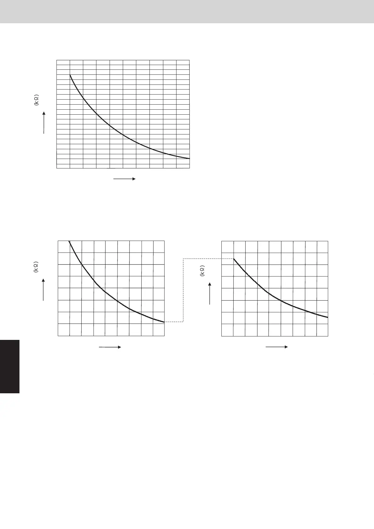
8. Thermister Characteristics Curve
(4) Indoor suction air (room) temp. sensor (TA)
Indoor discharge air temp. sensor (BL)
(5) Indoor coil temp. sensor (E1, E3)
40
35
30
25
20
15
10
5
0
-20 -15 -10-505101520
8
7
6
5
4
3
2
1
0
20 30 40 50 60
10 555045403530252015
10
9
8
7
6
5
4
3
1
2
Resistance
Resistance
Resistance
Temperature (˚C)
Temperature (˚C)
Temperature (˚C)
6. Inspection and Characteristics of Parts
2WAY SYSTEM
Trouble Diagnosis
Compressor
Type
9VD650XAA21
unit : ohm
0.735
0.715
0.715
Resistance
(at 20°C)
(6) Coil Resistance of Compressor Motor
(7) Characteristics of Sensor
Resistor (kΩ)
Resistor (kΩ)
● Outdoor air temp. sensor (TO)
●
Compressor intake temp.
sensor (SCT)
Temperature(
°C)
Temperature(
°C)
● Outdoor coil liquid temp.
sensor (EXL)
● Outdoor coil gas temp.
sensor (EXG)
●
Temp. sensor at refrigerant
gas outlet of dual-tube (SCG)
40
35
30
25
20
15
10
5
0
-10-15-20 20
20 30 40 50 60
151050-5
8
7
6
5
4
3
2
1
0
Resistor (kΩ)
Temperature(°C)
●
Compressor discharge gas temp. sensor (DISCH)
0908070605040302010
0
40
60
80
100
120
140
160
180
200
20
U - V
U - W
V - W
SM830289-00_Sec6.indd 24SM830289-00_Sec6.indd 24 2021/01/29 16:15:442021/01/29 16:15:44