Mini VRF SYSTEM
Test Run
7 - 14
7
4. Auto Address Setting
Display During Auto Address Setting
On the surface of outdoor unit control PCB
LED
Blinks alternately
* Do not short circuit the A.ADD pin again during auto address setting.
LEDs 1 and 2 go out and address setting is interrupted.
* When auto address setting is normally completed, both LEDs 1 and 2 go out.
In other cases, correct settings by referring to the following table and perform auto address setting
again.
Contents of LEDs 1 and 2 on outdoor unit control PCB
: Illuminating
: Blinking
: Go out
LED 1 LED 2 Contents of display
After turned on power (not during auto address setting), it is entirely impossible to communicate with
the indoor unit in the system.
After power is turned on (and auto address setting is not in progress), one or more indoor units are
conrmed in that system; however, the number of indoor units does not match the number that was
set.
This status remains even if the indoor unit address (indoor EEPROM item code : 13) is set more than
13 indoor units. In this case, be sure to set the indoor unit address less than 12.
Under auto address setting
Alternately
Auto address setting completed
There are inconsistencies between the number of indoor units and setting number of indoor units.
(at the time of auto address setting)
Simultaneously
See “7. Self-Diagnosis Function Table and Contents of Alarm Display”.
Alternately
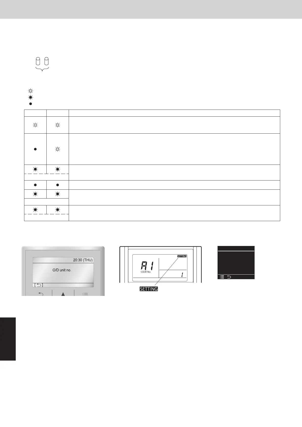
Display of remote controller
Request concerning recording the indoor/outdoor unit combination Nos.
After auto address setting has been completed, be sure to record them for future reference.
List the outdoor main unit system address and the addresses of the indoor units in that system in an easily visible
location (next to the nameplate), using a permanent marking pen or similar means that cannot be abraded easily.
Example: (Outdoor) 1 - (Indoor) 1-1, 1-2, 1-3… (Outdoor) 2 - (Indoor) 2-1, 2-2, 2-3…
These numbers are necessary for later maintenance. Please be sure to indicate them.
Auto address
[]
O/D unit no. 1
Assigning
Cancel
Auto address
1
Assigning
Blinking “
” indicator
CZ-RTC5B CZ-RTC4 CZ-RTC6 series
CZ-RTC6 series (Wired Remote Controller)
(1) Keep pressing the , and buttons simultaneously for 4 or more
seconds.
The “Maintenance func” screen appears on the LCD display.
Maintenance func
XX / XX
[][]
ECONAVI
nanoeX
RC. setting mode
(2)
Press the or button to see each menu.
Select “Simple settings” on the LCD display and press the button.
(3) The “Simple settings” screen appears on the LCD display.
Select the “Unit no.” by pressing the or button for changes.
The indoor unit fan operates only at the selected indoor unit.
(4)
Press the button and select “YES” to restart.
Maintenance func
XX / XX
[][]
Simple settings
Detailed settings
Auto address
Simple settings
[][]
Unit no.
Code no.
1-1
01
Set data 00010001
Checking the indoor unit addresses
Use the remote controller to check the indoor unit address.
SM830289-01_欧州向け R32 mini VRF 8,10HP SM&TRSM.indb 14SM830289-01_欧州向け R32 mini VRF 8,10HP SM&TRSM.indb 14 2021/05/07 10:16:492021/05/07 10:16:49