Mini VRF SYSTEM
Control Functions - Outdoor unit
1 - 8
1
2. Compressor Control
4. Special Control
2WAY VRF SYSTEM
Control Functions
Items Remarks Indication on PCB
This valve turns OFF at cooling mode, and turns ON at heating mode.
When the outdoor unit stops, the 4-way valve maintains in the same state as before.
Regarding the operation in defrost mode, see Section “8. Defrost Control”.
Solenoid valve
Motor Operated Valve
Crankcase heater
4-way valve
Oil recovery valve
MOV for heat exchanger
MOV for Sub cooler
Crankcase heater
20S
ORVR
MOV1
MOV4
CH
(1) 4-way Valve [20S]
This valve turns ON for 5 seconds before the inverter compressor starts. After the inverter compressor starts, the
valve is ON for 2 minutes. After that, it turns OFF.
ORVR valve
5 seconds 2 minutes
Inverter compressor starts
Compressor
Valve turns ON Valve turns OFF
This valve turns ON for 30 seconds after the outdoor unit stops. After that, it turns OFF.
This valve turns ON when the high pressure is too high.
This valve turns OFF when the high pressure goes down.
This valve turns ON when the high pressure switch is activated.
This valve stays ON for 10 seconds after the high pressure switch returns in normal.
After that, it turns OFF.
This valve might turn ON when the system capacity is excessive although the inverter compressor operates at
minimum frequency.
This valve turns ON while the discharge temperature of the compressor is low.
This valve turns ON during the operation of 4-way valve control.
(2) Oil Recovery Valve [ORVR]
The purpose of this valve is to recover oil from the oil separator to the compressor and is to adjust the
capacity and pressure.
This valve is always OFF when outdoor unit is stopped.
Current protection
This restriction protects the compressor and controls the compressor electric current simultaneously.
The current limitation value changes to “normal status” and “overload status” according to the outdoor
temperature.
The primary and secondary current values of the inverter compressors are measured.
3
unit: Ampere
Type of outdoor unit 8HP 10HP
Primary
Limit current 1 23.0 23.0
Maximum current 1 H 12.7 18.5
Maximum current 1 L 11.7 17.5
Type of outdoor unit 8HP 10HP
Secondary
Limit current 2 24.3 24.3
Maximum current 2 H 20.5 20.5
Maximum current 2 L 19.5 19.5
Stop If this current is detected at regular intervals, alarm appears.
Limit current 1, 2
Frequency of inverter compressor goes down.
Max. current 1H, 2H
Frequency of inverter compressor cannot increase.
Max. current 1L, 2L
Frequency of inverter compressor can increase.
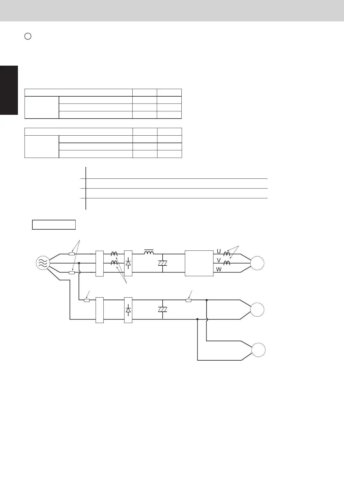
Inverter layout
Power
supply
Noise filter
Noise filter
L1
L2
L3
Primary CT1
Diode
bridge
IPM
(CM)
Compressor
Fan motor 1
Secondary CT
Reactor
FuseFuse
Fuse
N
Fuse
Diode
bridge
Fan motor 2
SM830289-01_欧州向け R32 mini VRF 8,10HP SM&TRSM.indb 8SM830289-01_欧州向け R32 mini VRF 8,10HP SM&TRSM.indb 8 2021/05/07 10:10:272021/05/07 10:10:27