1-16
1
1100
67
67
1310
964
(60) (60)
1070
132
45
1
2
6
1138
467
422
7
8
320
41
434
100
100
60
1220
156
131207
45
43
100
100
50
300
40
479
23
1205
1310
1334
1453
467
65
77
479
264
27
3
5
4
1200
1170
9 ×100 pitch = 900
(Suspension bolt pitch)
4-37×12 hole
(For suspension bolt)
Electrical component box
28-ø3.2 hole
26-ø3.2 hole
(Suspension bolt pitch)
10 ×100 pitch = 1000
Unit : mm
Refrigerant liquid tubing (Flare) Type 200: ø9.52
Type 250: ø12.7
Refrigerant gas tubing (Brazing) ø25.4 mm
Power supply port
Communication wiring port
Port for optional wiring part
Drain port 25A
Air intake duct connecting side flange
Air discharge duct connecting side flange
1-4. Dimensional Data
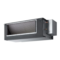
(A) Indoor Units: High Static Pressure Ducted Type
S-200PE2E5
S-250PE2E5
1
2
3
4
5
6
7
8
1
(A) Indoor Units: High Static Pressure Ducted Type
S-200PE1E8A
479
300
100
2
100 100
42
1428
1310
71110051
1170 (Suspension bolt pitch)
964
9 × 100P = 900
4 - 37
×
12
(Hole for suspension bolt)
26-ø3.5 (Holes all around)
28-ø3.5 (Holes all around)
10 × 100P = 1000
106
44
1070
1310
67 67
1200 (Suspension bolt pitch)
113
(236) 364364
1334
60
43320
10050
178
23
209 344
1230
41
Refrigerant liquid line 200: ø9.52, 250: ø12.7
Refrigerant gas line ø25.4
Power supply outlet
Drain port (OD 32 mm)
Duct connection for suction
Duct connection for discharge
unit: mm
Sec1.indd 16 2014/11/07 10:27:52
 Loading...
