23
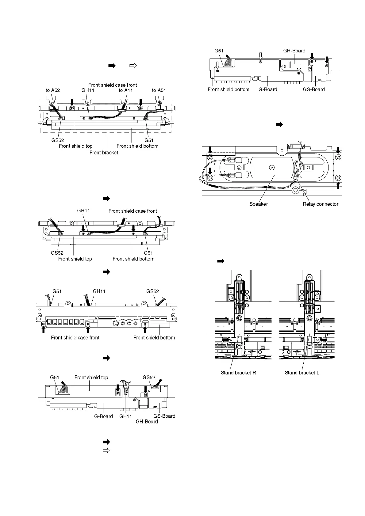
7.16. Remove the Front bracket
1. Unlock the cable clampers to free the cable.
2. Disconnect the connectors (A11, A51 and A52). (See sec-
tion 7.6.)
3. Remove the screws (×2 , ×2 ) and remove the
Front bracket.
7.17. Remove the G-Board, GS-
Board and GH-Board
1. Remove the Front bracket. (See section 7.16.)
2. Remove the screws (×2 ).
3. Remove the screws (×3 ).
4. Remove the Front shield case front.
5. Disconnect the connectors (GH11 and GS52).
6. Remove the screws (×2 ).
7. Remove the Front shield top.
8. Remove the GH-Board.
9. Remove the screws (×2 ) and remove the GS-Board.
10. Remove the screws (×3 ).
11. Disconnect the connector (G51) and remove the G-
Board.
7.18. Remove the Speakers
1. Disconnect the relay connectors
2. Remove the screws (×4 each) and remove the
Speaker (L, R).
7.19. Remove the Plasma panel sec-
tion from the Cabinet assy
(glass)
1. Remove the stand brackets (left, right) fastening screw
(×1 each).