1 Applicable signals 4
2 Safety Precautions
5
2.1. General Guidelines
5
3 Prevention of Electrostatic Discharge (ESD) to
Electrostatically Sensitive (ES) Devices
6
4 About lead free solder (PbF)
7
5 Service Hint
8
6 Plasma panel replacement method
9
6.1. Remove the Back cover
9
6.2. Remove the fan
9
6.3. Remove the rear terminal cover
9
6.4. Remove the tuner unit
9
6.5. Remove the DG-Board
10
6.6. Remove the H-Board
10
6.7. Remove the P-Board
10
6.8. Remove the side AV unit and the side AV bracket.
11
6.9. Remove the G-Board and GS-Board
12
6.10. Remove the PB-Board
12
6.11. Remove the D-Board
12
6.12. Remove the SU-Board
13
6.13. Remove the SD-Board
13
6.14. Remove the SC-Board
13
6.15. Remove the SS-Board
14
6.16. Remove the stand brackets
14
6.17. Remove the cabinet assy mounting metal.
14
6.18. Remove the C1-Board
15
6.19. Remove the C2-Board
15
6.20. Remove the C3-Board
15
6.21. Remove the C4-Board
16
6.22. Remove the Plasma panel section from the Cabinet assy
(glass)
16
6.23. Remove the K-Board and the S-Board
16
6.24. Replace the plasma panel (finished)
17
7 Caution statement
18
7.1. Caution statement.
18
8 Location of Lead Wiring
19
8.1. Lead of Wiring (1)
19
8.2. Lead of Wiring (2)
20
8.3. Lead of Wiring (3)
21
8.4. Lead of Wiring (4)
22
8.5. Lead of Wiring (5)
23
8.6. Lead of Wiring (6)
24
9 Self-check Function
25
9.1. Check of the IIC bus lines
25
9.2. Power LED Blinking timing chart
26
9.3. No Power
27
9.4. No Picture
28
9.5. Local screen failure
29
10 Service Mode
30
10.1. How to enter into Service Mode
30
10.2. Service tool mode
32
11 Adjustment Procedure
33
11.1. Driver Set-up
33
11.2. Initialization Pulse Adjust
34
11.3. P.C.B. (Printed Circuit Board) exchange
34
11.4. Adjustment Volume Location
35
11.5. Test Point Location
35
12 White Balance Adjustment
36
12.1. White balance adjustment
36
13 Hotel mode
38
14 Conductor Views
39
14.1. P-Board
39
14.2. PB-Board
42
14.3. G,GS,K and S-Board
43
14.4. H-Board
44
14.5. DG-Board
47
14.6. D-Board
50
14.7. C1-Board
53
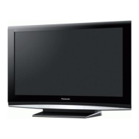
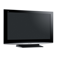
FEATURES 3D Y/C FILTER
CLOSED CAPTION V-Chip
Photo Viewer HDAVI Control 2
Dimensions (W × H × D)
Including pedestal 44.7 ” × 27.1 ” × 13.0 ” (1,134 mm × 688 mm × 330 mm)
TV Set only 44.7 ” × 25.3 ” × 4.6 ” (1,134 mm × 641 mm × 116 mm)
Mass
Including pedestal 92.6 lb. (42 kg)
TV Set only 77.2 lb. (35 kg)
Note:
·
Design and Specifications are subject to change without notice. Mass and Dimensions shown are approximate.
CONTENTS
Page Page
2
TH-42PZ77U

 Loading...