9 Measurements and Adjustments
9.1. Adjustment Procedure
9.1.1. Driver Set-up
9.1.1.1. Item / Preparation
1. Input a white signal to plasma video input.
2. Set the picture controls as follows.
Picture menu: Dynamic
PNR: Min
Aspect: 16:9
Caution
1. First perform Vsus adjustment.
2. The Vscn voltages are measured from the Vad (Vad_base), but may be measured from the GND (GND_base) in an
unavoidable case.
9.1.1.2. Adjustments
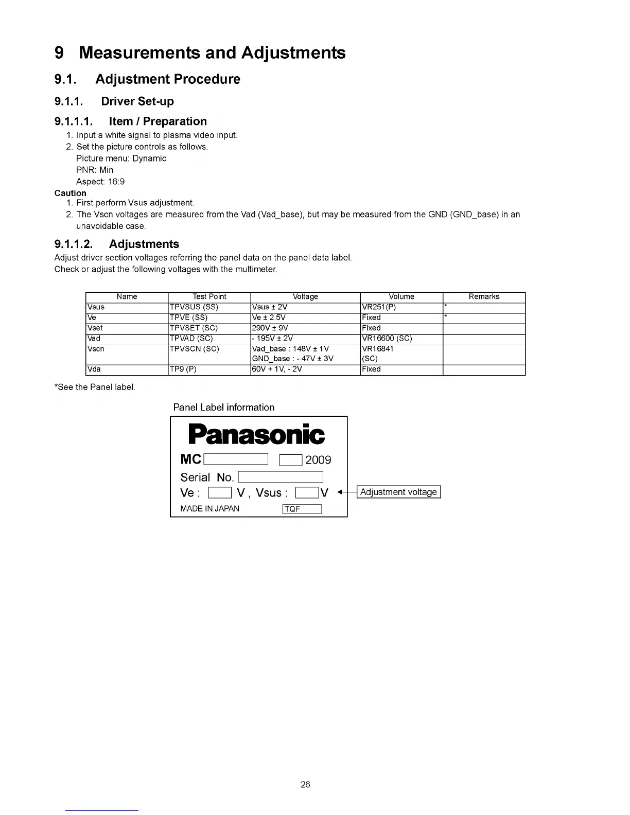
Adjust driver section voltages referring the panel data on the panel data label.
Check or adjust the following voltages with the multimeter.
Name Test Point Voltage Volume Remarks
Vsus TPVSUS (SS) Vsus ± 2V VR251(P)
*
Ve TPVE (SS) Ve ± 2.5V Fixed
*
Vset TPVSET (SC) 290V ± 9V Fixed
Vad TPVAD (SC) - 1 9 5V ± 2V VR16600 (SC)
Vscn TPVSCN (SC) Vad_base : 148V ± 1V
GND_base : - 47V ± 3V
VR16841
(SC)
Vda TP9 (P) 60V + 1V, - 2V Fixed
*See the Panel label.
26