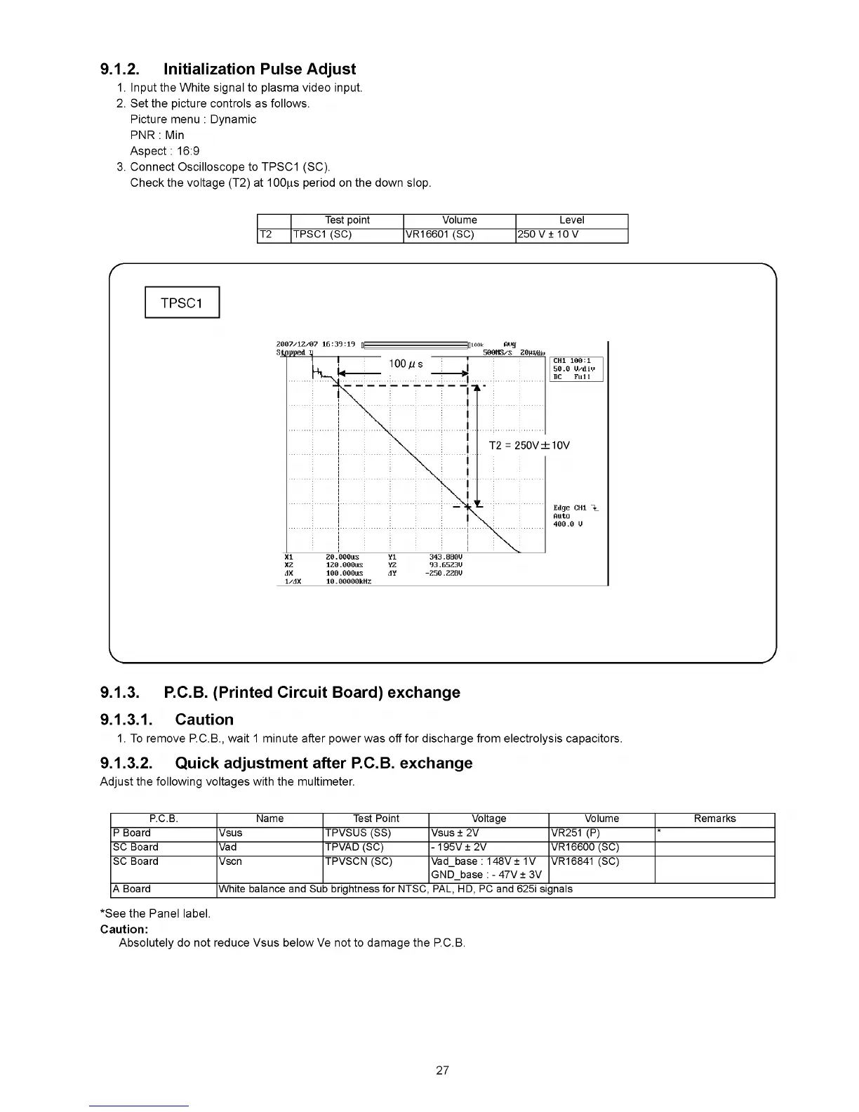
9.1.2. Initialization Pulse Adjust
1. Input the White signal to plasma video input.
2. Set the picture controls as follows.
Picture menu : Dynamic
PNR : Min
Aspect : 16:9
3. Connect Oscilloscope to TPSC1 (SC).
Check the voltage (T2) at 100|is period on the down slop.
Test point Volume Level
T2 TPSC1 (SC) VR16601 (SC) 250 V ± 10 V
TPSC1
2007/12/07 1 6 :3 9 :1 9 fll Iniook ймд
Sa p p e d TJ
________ ______________
500MS/S 20HS/dui
1
U
------
I
-----
100 Ц s
— 1
CHI 100:1
50.0 U/diM
DC F u ll
' \ Г
l "
b10V
Edge CHI
Auto
400.0 U
i
i
1'2 = 250V d
i
!
1
>
X I 20.000US Y1 343.880U
X2 120.000US Y2 93.65Z3U
dX 100.O00US dY -250.ZZBU
1/dX 1 0 .00000kHZ
9.1.3. P.C.B. (Printed Circuit Board) exchange
9.1.3.1. Caution
1. To remove PC.B., wait 1 minute after power was off for discharge from electrolysis capacitors.
9.1.3.2. Quick adjustment after P.C.B. exchange
Adjust the following voltages with the multimeter.
P.C.B. Name Test Point Voltage Volume Remarks
P Board Vsus TPVSUS (SS) Vsus ± 2V VR251 (P)
*
SC Board Vad TPVAD (SC) - 195V ± 2V VR16600 (SC)
SC Board Vscn TPVSCN (SC) Vad_base : 148V ± 1V
GND_base : - 47V ± 3V
VR16841 (SC)
A Board White balance and Sub brightness for NTSC, PAL, HD, PC and 625i signals
*See the Panel label.
Caution:
Absolutely do not reduce Vsus below Ve not to damage the PC.B.
27
 Loading...