Home
Panasonic
Plasma TV
TX-PR42U10
Page 76
Panasonic TX-PR42U10 - Page 76
139 pages
Manual
Save Page as PDF
To Next Page
To Next Page
To Previous Page
To Previous Page
Loading...
1
2
.2
6.
C
1-B
oar
d
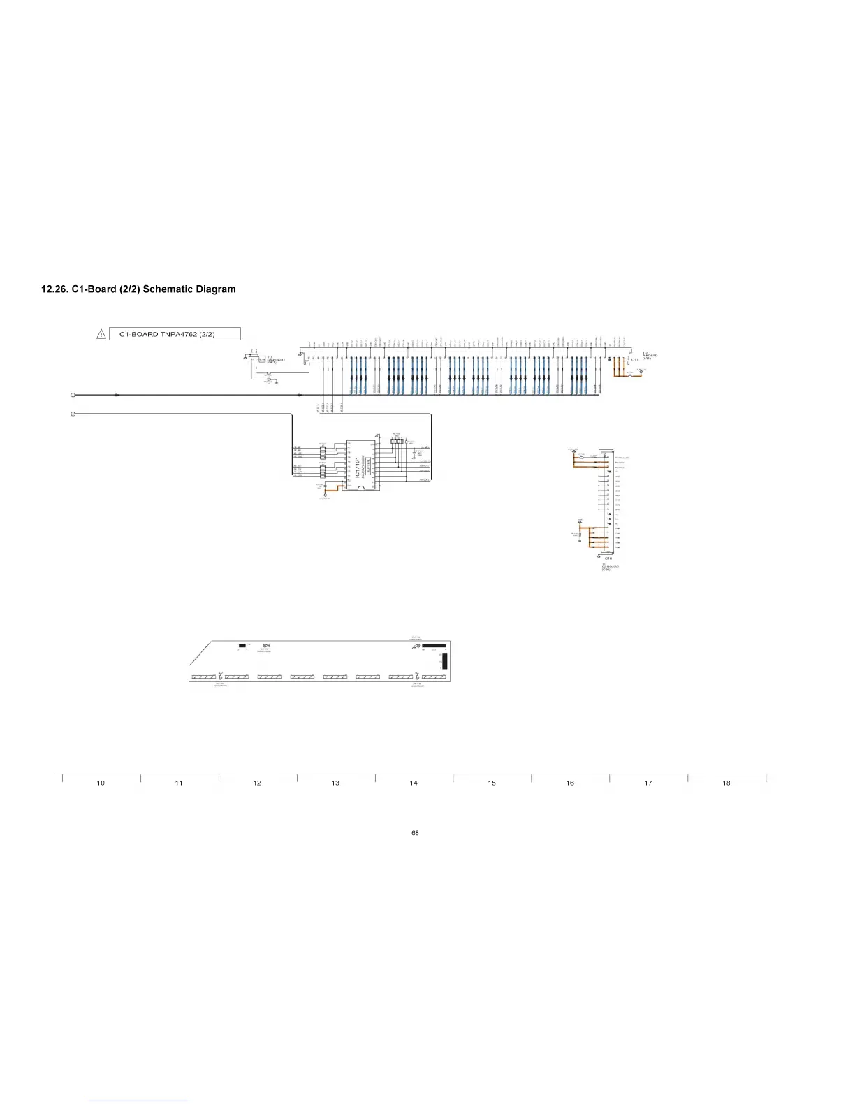
(2/2
)
S
c
h
e
m
a
ti
c
Diagram
A
C
1
-
B
O
A
R
D
T
N
P
A
4
7
6
2
(
2
/
2
)
,
,
,
,
,
,
,
2
2
,
.
,
.
.
.
.
.
s
'
a
1
s
'
a
1
s
s
'
а
1
s
'
a
'
s
£
£
s
s
'
s
'
s
'
s
'
s
s
'
s
'
s
'
s
1
0
1
1
1
2
1
3
1
4
1
5
1
6
1
7
1
8
(
C
2
0
)
K
4
A
D
0
1
Z
0
0
0
0
1
6
8
75
77
Table of Contents
Main Page
Table of Contents
2
General Guidelines
3
Measuring Network for Touch Currents
3
Safety Precautions
3
Touch-Current Check
3
A Rn in G
4
Prevention of Electrostatic Discharge (ESD) to Electrostatically Sensitive (ES) Devices
4
Warning
4
About Lead Free Solder (Pbf)
5
Suggested Pb Free Solder
5
Service Hint
6
Service Navigation
6
Applicable Signals
7
Specifications
8
How to Enter into Service Mode
9
Key Command
9
Contents of Adjustment Mode
10
How to Exit
10
Display of SOS History
11
Exit
11
POWER on Time, On/Off
11
Service Tool Mode
11
Hotel Mode
12
Check of the IIC Bus Lines
13
Check Point
13
Screen Display
13
Troubleshooting Guide
13
Power LED Blinking Timing Chart
14
No Power
15
No Picture
16
Local Screen Failure
17
SC Jig
18
Service Fixture & Tools
18
Disassembly and Assembly Instructions
19
Remove the Rear Cover, Remove the P-Board
19
Remove the Side Terminal Cover and Rear Teminal Cover
19
Remove the A-Board
20
Remove the Tuner Unit
20
Remove the Control Button Unit
21
Remove the GK-Board
21
Remove the Speakers
21
Remove the SU-Board
21
Remove the SC-Board
22
Remove the SD-Board
22
Remove the SS2-Board
22
Remove the C1-Board
23
Remove the C2-Board
23
Remove the Hanger Metals and the Stand Brackets
23
Remove the SS-Board
23
Remove the Plasma Panel Section from the Cabinet Assy (Glass)
24
Remove the S-Board
24
Remove the Front Glass
25
Remove the K-Board
25
Replace the Plasma Panel
25
Driver Set-Up
26
Item / Preparation
26
Measurements and Adjustments
26
Initialization Pulse Adjust
27
P.C.B. (Printed Circuit Board) Exchange
27
Quick Adjustment after P.C.B. Exchange
27
Adjustment Volume Location
28
Test Point Location
28
Sub-Contrast Adjustment
29
RF White Balance Adjustment
31
1080I White Balance Adjustment
32
Main Block Diagram
33
Block Diagram
34
Wiring Connection Diagram
39
Schematic Diagram
43
P-Board Schematic Diagram
45
GK, К and S-Board Schematic Diagram
47
A-Board Schematic Diagram
49
C1 -Board (1/2) Schematic Diagram
74
C2-Board Schematic Diagram
77
Printed Circuit Board
77
SC-Board Schematic Diagram
79
SS-Board Schematic Diagram
83
P-Board
85
Printed Circuit Board
85
P-BOARD (Component Side) ETX2MM747MFE
88
K, К, S and SS2-Board
89
K-BOARD (Component Side) TXN/K1 ETUR
90
K-BOARD (Foil Side) TXN/K1ETUR
90
A-BOARD (Foil Side) A-PR42U10
91
Exploded View and Replacement Parts List
91
A-BOARD (Component Side) A-PR42U10
92
C1-Board
94
C2-Board
95
SC-Board
96
SC-BOARD (Component Side) TXNSC11XBH
100
SS-Board
101
Exploded View and Mechanical Replacement Parts List
104
Packing 1
105
Packing 2
106
Mechanical Replacement Parts List
107
Abbreviation of Part Name and Description
111
Electrical Replacement Parts List
111
RTL (Retention Time Limited)
111
Related product manuals
Panasonic TX-PR42UT30
114 pages
Panasonic TX-PR42C2
121 pages
Panasonic TX-PR42G10
140 pages
Panasonic TX-PR42C10
123 pages
Panasonic TX-PR42S20
128 pages
Panasonic TX-PR50VT50
119 pages
Panasonic TX-PF42G30
117 pages
Panasonic TX-P42U10E
64 pages
Panasonic TX-P50X60E
48 pages
Panasonic TX-P50X50E
60 pages
Panasonic TX-P42S20L
128 pages
Panasonic TX-P42G20E
131 pages



 To Next Page