Table of Contents
3
Specifications Table...................................5
1.1 Fax Function.............................................5
1.2 Printer Function ......................................13
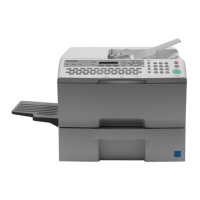
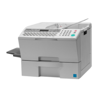
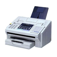
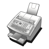
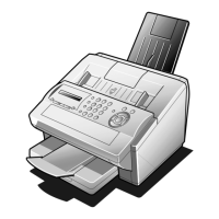
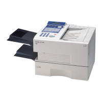
1.3 External View..........................................14
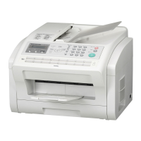
1.4 Control Panel..........................................16
Disassembly Instruction...........................17
2.1 General Disassembly Flowchart.............17
2.2 Power Cord (1108), Telephone Line
Cable (1107), Document Return Tray
(138 and 139), Recording Paper Tray
(1106), Paper Cassette (1018) ...............18
2.3 Sub Rear Cover (114), Rear Cover (108),
Left Side Cover (107), Front Cover (105),
Speaker (133)........................................19
2.4 Paper Guide Cover (110), Transmit
Guide (117), SNS Assembly (121) .........21
2.5 Low Voltage Power Supply Unit (502),
FCB PC Board (522), LCU PC Board
(519), LPC PC Board (555), Control
Panel Unit, PNL PC Board (214) ............23
2.6 Transmitter Chassis (301), Scanner
Assembly (340), LED Array Assembly
(333), Verification Stamp Assembly........27
2.7 ADF Roller (323), Pre-Feed Roller (325),
Eject Roller (330), Feed Roller (328),
Transmission Gear Assembly, Transmit
Motor (346) .............................................29
2.8 Toner Sensor (639), Timing Sensor
(610), Bias Transfer Roller (630) ...........32
2.9 Fuser Unit (431), Fuser Lamp (408),
Thermistor Assembly (405), Paper Exit
Sensor (610)...........................................34
2.10 Fuser Roller (414), Pressure Roller
(409), Eject Roller (422)..........................38
2.11 Fan Duct (520), Printer Motor (650),
Motor Bracket (641)................................40
2.12 Laser Unit (429), Feed Roller (618),
Paper Feed Roller (746), Clutch Gear
Assembly (660), Paper Feed Solenoid
(744), Fan Unit (622) ..............................42
2.13 ILS PC Board (621), No Paper Actuator
(609), Catch Magnet (730)......................44
2.14 High Voltage Power Supply
(HVPS) (506) ..........................................45
2.15 Parallel Port Interface Assembly (671) ...46
2.16 Screw Identification Template.................47
Maintenance, Adjustments and
Check Points ........................................... 48
3.1 Required Tools ...................................... 48
3.2 Periodic Maintenance Points.................. 48
3.3 Periodic Maintenance Check List........... 49
3.4 Updating the Firmware........................... 50
3.5 ADF Pressure......................................... 51
3.6 Printer Unit Test ..................................... 52
3.7 General Circuit Diagram......................... 53
3.8 FCB PC Board ....................................... 56
3.9 LPC PC Board........................................ 84
3.10 LCU PC Board ....................................... 93
3.11 SRU PC Board (Optional) ...................... 96
3.12 Low Voltage Power Supply PCB
(POW) .................................................... 98
3.13 High Voltage Power Supply PCB
(HVPS)................................................. 100
3.14 CST2 PC Board (Optional)................... 102
3.15 CST3 PC Board (Optional)................... 106
3.16 PRT PC Board ..................................... 110
3.17 EP PC Board (Optional) ....................... 115
3.18 G3B PCB (Optional)............................. 116
Troubleshooting..................................... 117
4.1 Initial Troubleshooting Flowchart ......... 117
4.2 Improper LCD Display..........................118
4.3 Information Codes (INFO. CODES)..... 119
4.4 Printed Copy Quality Problems............132
4.5 Document Feeder (ADF)...................... 148
4.6 Communications .................................. 151
4.7 Information Code Table........................ 157
4.8 Diagnostic Codes.................................164
Service Modes.......................................171
5.1 Service Mode (For Facsimile) .............. 171
System Description................................215
6.1 Mechanical Operation ..........................215
6.2 Electrical Circuit Explanation................226
 Loading...