52
10 The cutting technique and condition (continue)
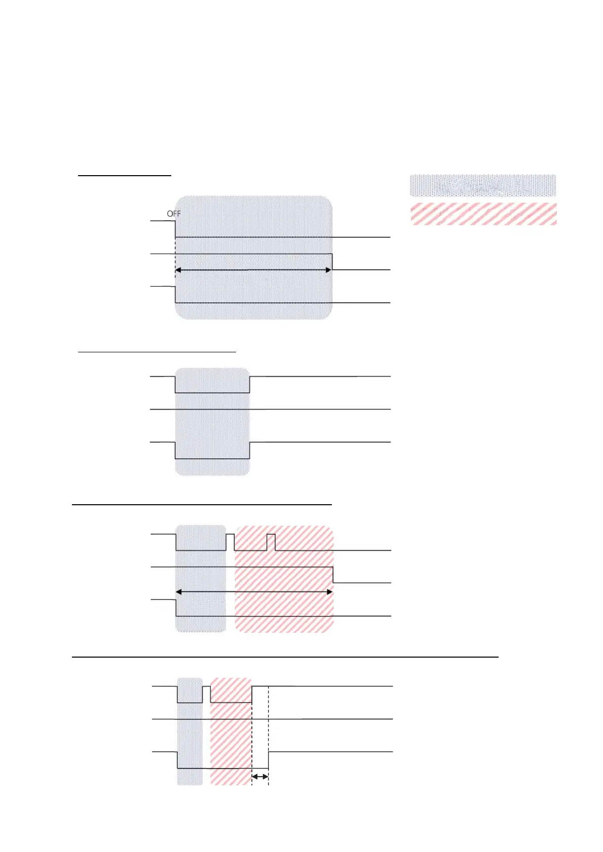
10.7 The air post flow sequence chart
To protect cutting tip and electrode, after cutting finishes air is blown around 20s to cool down the torch.
The sequences of air post flow (about 20s) are shown here:
Air
Cutting
current
The cutting
torch switch
During post flow around 20s after
cutting finishes, key operation is
not functional.
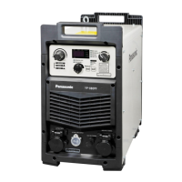
When cutting starts after
operation limiting period, pre-
procedure is omitted, i.e. cutting
immediately start after pressing
the cutting torch switch.
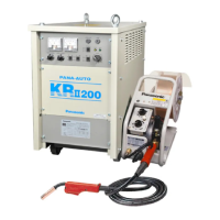
When the cutting torch switch is
pressed during the operation
limiting period, operation limit is
removed and general operation
can be executed. However after
flow (about 20s) lasts.
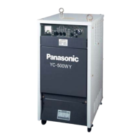
Operation limit is removed. When
cutting starts on the status
keeping after flow, 1s pre-flow
time is added.
·General after flow
·When the cutting torch switch is operated and cutting starts during after flow procedure
after flow (20 s or so)
No pre-flow
after flow (20 s or so)
1s pre-flow time
During after flow
Operation limiting time
Operation enable time
Air
Cutting current
The cutting
torch switch
Air
Cutting
current
The cutting
torch switch
Air
Cutting
current
The cutting
torch switch
·During after flow, cutting starts
·During after flow, the cutting torch switch is operated