5
4
USER MANUALSECURITY-SERVICE SYSTEM PANDORA CAMPER
EN
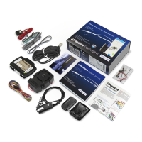
System set
1. User manual and wiring diagram 1
2. Remote control D030 1
3. Radio tag BT760 1
4. Owner’s personal card 1
5. Base unit 1
6. External LED/VALET button 1
7. Beeper 1
8. Wireless door sensor DMS-100 BT 4
9. Siren PS-330 1
10. Main cable of the base unit 1
11. Additional cable of the base unit 1
12. External temperature sensor 1
13. Blocking relay 2
14. Magnetic reed sensor 2
15. Fastening kit 1
16. Packaging 1
! The manufacTurer reserves The righT To change The sysTem seT and consTrucTion of The producT To improve iTs
Technological and operaTional parameTers wiThouT noTificaTion.
Read the following section before using the system
Carefully read this manual before starting installation and using the security-service system. Pay
attention to text marked with
!
!
The sysTem is a complex Technical producT. sysTem insTallaTion and configuraTion musT be carried ouT only by a
skilled professional.
!
feaTures and sysTem modes, conTrol of The vehicles zones depends on The Type of connecTion and sysTem seTTings,
original vehicle operaTion logic and Trim.
! The sysTem seT includes an “owner’s personal card”. This card conTains informaTion under a proTecTive layer ThaT
is inTended only for The owner of The sysTem. make sure ThaT The proTecTive layer on The owner’s plasTic card is inTacT
afTer The insTallaTion of The sysTem.
!
read The “owner’s personal card” secTion of This manual before erasing The proTecTive layer.
!
The sysTem has a gsm inTerface. ask an insTaller who has insTalled The sysTem To check The gsm funcTions
operaTion using your phone:
• dial 500* command To requesT coordinaTes (see The “conTrol The sysTem from a phone” secTion).
• Trigger alarm when The sysTem is armed. The sysTem musT call your phone number (“main owner’s phone number”).
To quickly change The “main owner’s phone number”, Turn on The igniTion when The sysTem is disarmed and call The
sysTem phone number. waiT for The answer, Then press and hold The buTTon on The radio Tag for 2 seconds (unTil The
second flash of The send indicaTor). release The buTTon, The sysTem will recognize The incoming phone number as
The “main owner’s phone number”.
• check The “guesT pin-code” (facTory defaulT value is 1-2-3-4). call The sysTem from an “addiTional phone number”
or from any oTher phone number unknown for The sysTem.
! The sysTem can work wiTh a mobile applicaTion. iT is required To creaTe an accounT, add The sysTem To your accounT,
pair your mobile phone wiTh The sysTem. ask an insTaller To help you To configure The mobile applicaTion.
! when sysTem insTallaTion is finished:
• check ThaT The “insTallaTion cerTificaTe” and “warranTy card” are filled ouT. These documenTs may be required for
conTacTing The cusTomer supporT.
• check The sysTem operaTion and funcTions wiTh a specialisT.
• we recommend ThaT you mark each working funcTion wiTh a
sign in The “conTrol The sysTem” secTion.
• ask an insTaller To mark The layouT of The sysTem componenTs on The diagram. This informaTion may be required for
diagnosTic/configuring or emergency deacTivaTion of The sysTem.
• we recommend ThaT you change The defaulT value of The “service pin-code” (1-1-1-1). ask an insTaller To change
The “service pin-code”.
wriTe down and remember a new value of The “service pin-code”
• we recommend ThaT you change The defaulT value of The “guesT pin-code” (1-2-3-4). (see The “changing seTTings
from a phone” secTion -> 5* addiTional seTTings -> 1* changing The guesT pin code.
wriTe down and remember a new value of The “guesT pin-code”
• if The “code immobilizer (pin-To-drive)” funcTion is implanTed:
wriTe down and remember The “immobilizer pin-code”
mark a buTTon (buTTon/lever/pedal) ThaT is used To enTer The “immobilizer pin-code” in The layouT diagram.