3
Installation
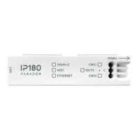
The Printer Module is connected to the control panel’s combus. Connect the four terminals labeled red, black, green, and yellow of the
module to the corresponding terminals on the control panel as shown in Figure 2 on page 22. See the EVO or DGP-848 Reference &
Installation Manual for the maximum allowable installation distance from the control panel.
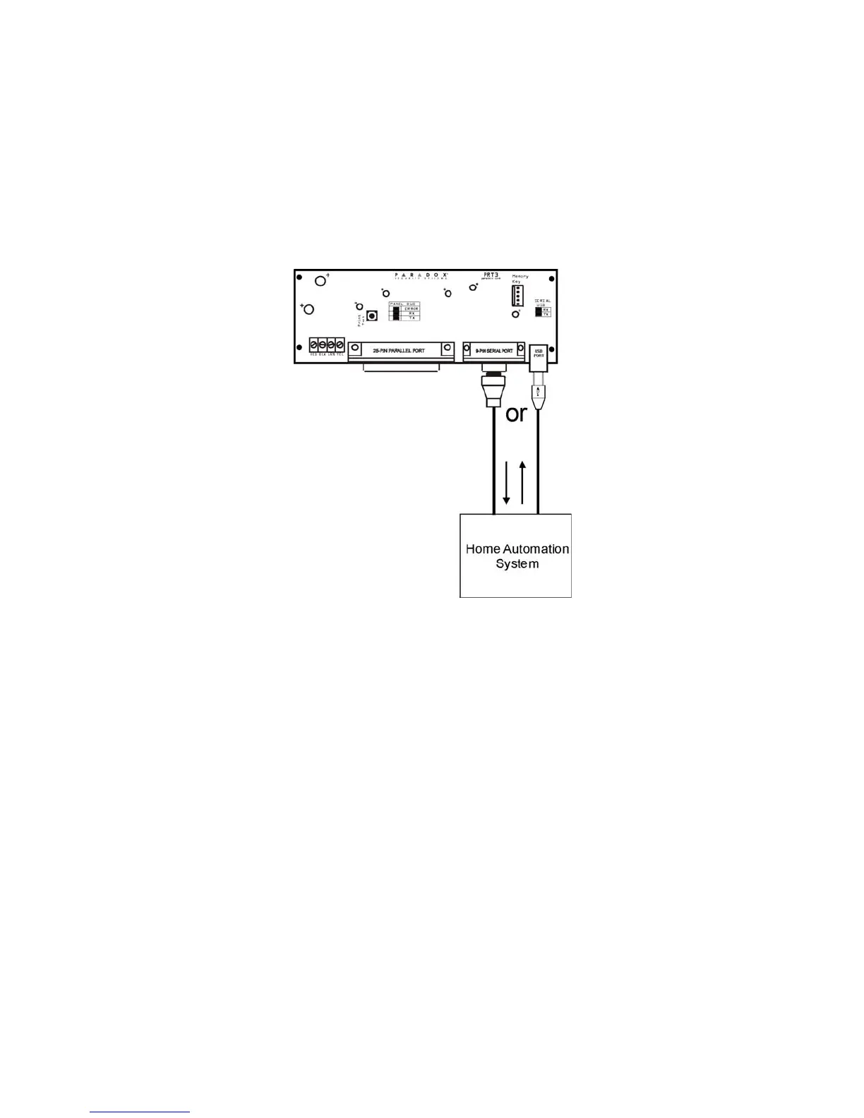
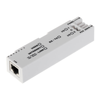
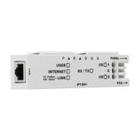
The home automation module must be connected directly to the Printer Module’s serial port (9-pin/ DB-9 connector). See Figure 2 on page
22 for an overview of the Printer Module’s connections, LEDs and connectors.
Overview
The following provides of an overview of how the Printer Module communicates with the home automation system.
Figure 1: Typical ASCII Application
Programming Sections
The following describes the programming sections which must be set when the Printer Module acts as an interface between a control panel
and a home automation module using the ASCII Protocol.
To access the Printer Module’s programming mode:
STEP 1: Press and hold the [0] key.
STEP 2: Enter the [
INSTALLER CODE].
STEP 3: Enter section [953] (DGP-848) / [4003] (EVO).
STEP 4: Enter the Printer Module’s 8-digit [
SERIAL NUMBER].
STEP 5: Enter the 3-digit [
SECTION] you want to program.
STEP 6: Enter the required data.
The Printer Module can also be programmed using the WinLoad Security Software (V2.62 or higher) or using the control panel’s Module
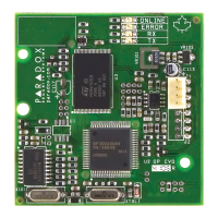
Broadcast feature. Refer to the panel’s Reference & Installation Manual for more details. Please note that the serial number can be located
on the Printer Module’s PC board.
• ASCII commands
(arm, disarm, panic, virtual
input open/close)
• Virtual PGM events
• System events
• Communication with
panel status