NVX80 Installation Manual 9
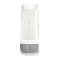
19. Insert the protective foam into the NVX80’s connector opening to prevent element infiltration to the serial
connector.
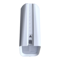
20. Slide the front section of the NVX80 onto the back cover of
the unit. The power up sequence will automatically start
(if power is being supplied) and takes about 30 seconds.
NOTE: Excessive force can damage pin connectors to the power block. Please always use caution when separating
the front and back panels.
21. Ensure the back panel and front cover are properly joined.
22. While the captive screw at the bottom of the unit is open, beg
in the power up process, and access the menus for
configuration settings (see Figure 9). For more information about these settings
, please see the NVX80 User Guide
(document NVX80-EU00).
23. Carefully tighten the captive screw found at the bottom
of unit, stopping when the green “Tamper Closed”
message appears on the OLED screen. Once the screw is properly fastened, it makes a connection which acts as the
cover tamper.
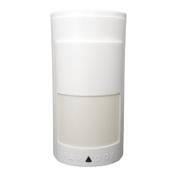
24. Slide the all-weather cover on (optional, for outdoor installations).
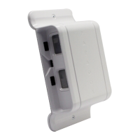
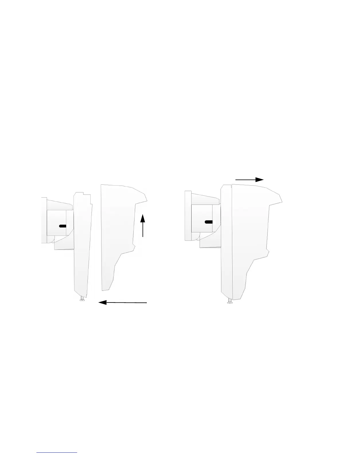
25. Mount the module. Do not tight
en the capture screw yet.
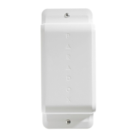
Figure 2: Separating the Module from the Bracket
 Loading...