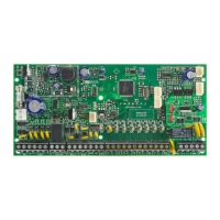
SP+ Series Programming Guide
7
Communicator
Cancel Communication
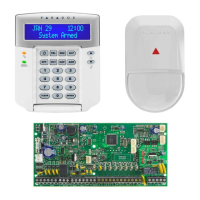
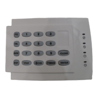
Keypad Programming
Assigning Keypad Zone Numbers
Assigning Keypad Zone Numbers TM50/TM70
Entry Point Zone Assignment (StayD)
Keypad Input/Output Configuration (K636 V2.0 and higher)
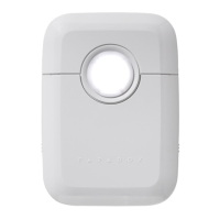
PGMs
Step Action Details
1
+ installer code
= flash; maintenance code may also be
used
2-
3
2 = backup phone #
3 = personal phone #1
4 = personal phone #2
5 = personal phone #3
6 = personal phone #4
7 = personal phone #5
4 Phone # +
ENTER
Enter phone number (up to 32 digits), and
then press
ENTER to proceed to the next phone
number, or go to step 5 if option 8 was
selected
Step Action Details
1
+ installer code
= flash; maintenance code may also be
used
2-
3 9
Cancels all communication with BabyWare and
PCS module
Step Action Details
1 E
NTER + installer code
ARM + STAY = flash; maintenance code may
also be used
2
Press and hold
for
three seconds
ARM + STAY = ON
3 Zone number +
ENTER
K35, K32, K32LCD, K32LX = two digits: 01 to 32;
K636, K10V/H = one digit: 1 to 0 (10)
NOTE: To erase a keypad zone number, press
CLEAR, and then ENTER.
Step Action Details
1
Press and hold
MENU
+
installer code
Enters into advanced programming
2 Program this unit Ensure that zone temperature input is enabled
3
Press keypad zone
number
Select your zone
Step Action Details
1 E
NTER + installer code
ARM + STAY = flash
2
Press and hold
OFF for
three seconds
ARM + STAY = ON
3 Zone number
K35, K32RF, K37, K32LCD, K32LX = two digits:
01 to 32; K636, K10V/H = one digit: 1 to 0 (10;
maximum ten zones); the first zone
programmed will be the designated entry
point and will flash; up to three more path
zones can be added – these zones will light up
and remain lit
4 E
NTER Press ENTER to save and exit
Step Action Details
1 E
NTER + installer code
ARM + STAY = flash
2
Press and hold
ENTER
for three seconds
ARM + STAY = ON
3Option 1
ON = output switches to ground following
system arming (blue wire, maximum150 mA)
OFF = input (keypad zone input)
4Option 2
ON = output N.C.
OFF = output N.O.
NOTE: When configuring as an output, clear the assigned keypad zone first.
Step Action Details
1
+ installer code
= flash; maintenance code may also be
used
2-
3 PGM number Two digits: 01 to 16
4 Enroll or erase PGM
Wireless PGM = press the
LEARN/TAMPER switch
or remove and re-install Jumper 2 (JP2) on
module; hardwired PGM = press
ENTER
5PGM type
1 = Follow button
or
2 = Follow button or
3 = Follow zone
4 = Follow alarm
5 = Follow bell
6 = Follow arm
7 = Follow Stay arm
8 = Follow Sleep arm
6
If PGM type is 1, 2, 3, or
4, enter activation
delay
1 = Follow
2 = 1 sec.
3 = 5 sec.
4 = 15 sec.
5 = 30 sec.
6 = 1 min.
7 = 5 min.
8 = 15 min.
9 = 30 min.
If PGM type is 5, proceed
to the next available
PGM
-
If PGM type is 6, 7, or 8,
enter
1 and/or 2 + ENTER
If system is partitioned, select partition(s), and
then press
ENTER to proceed to the next available
PGM
7
If PGM type is 1 or 2,
enter two-digit remote
control #
01 to 32 (00 = all remote controls); the control
panel proceeds to the next available PGM
If PGM type is 3, enter
two-digit zone #
01 to 32 (00 = all zones); the control panel
proceeds to the next available PGM
If PGM type is
4, enter 1
and/or
2 + ENTER
If system is partitioned, select partition(s), and
then press ENTER to proceed to the next available
PGM
NOTE: To erase a PGM, press and hold SLEEP for three seconds.