Parker Hannifin
Positive Homing (Homing Backup Enabled)
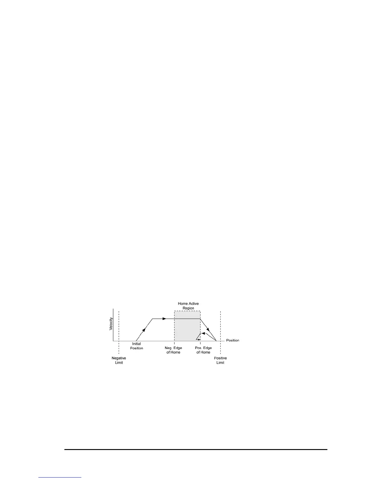
Figures C through F show the homing operation when the Home
Backup Enable bit is set (parameters 4600-4615).
The seven steps below describe a sample homing operation, as
illustrated in Figure C. Figures D through F show the homing
operation for different values of the Home Negative Edge Select
and Home Negative Final Direction bits—the Home Backup Enable
bit is set.
1. A positive home move is started with the JOG HOME X1
command at the JOG ACC and JOG JRK accelerations.
Default JOG ACC is 10 revs (or volts or inches) per sec
2
.
2. The JOGVEL velocity is reached (move continues at that
velocity until home input goes active).
3. The negative edge of the home input is ignored and the move
continues until the positive edge is detected. At this time the
move is decelerated at the JOG DEC and JOG JRK command
values.
4. After stopping, the direction is reversed and a second move
with a peak velocity specified by the JOG HOMVF value is
started.
5. This move continues until the positive edge of the home input is
reached.
6. Upon reaching the positive edge, the move is decelerated at
the JOG DEC and JOG JRK command values, the direction is
reversed, and another move is started in the positive direction
at the JOG HOMVF velocity.
7. As soon as the home input positive edge is reached, this last
move is immediately terminated. The load is at home and the
absolute position register is reset to zero.
Figure C
Homing Profile
Attributes:
• JOG HOME X1
• Home Backup
Enable (bit index
24) is set.
• Home Negative
Edge Select (bit
index 25) is clear.
• Home Negative
Final Direction (bit
index 26) is clear.
Making Motion 81
 Loading...


