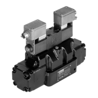
Directly operated and pilot operated directional control valves
Series D1VW / D1DW / D3W / D3DW / D31DW / D41VW / D81VW / D91VW
21
Translation from German
Parker Hannin Corporation
MSG11-5715-662 DCV UK.indd 21.07.22
Please note that with electrical connections the protective conductor (PE W) must be connected according to the
relevant regulations.
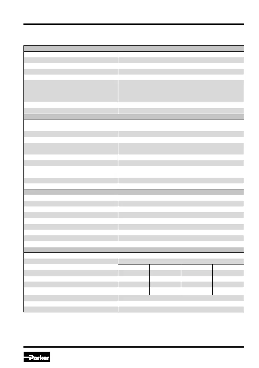
General
Design Directional spool valve
Actuation Solenoid
Series D81/D91
Nominal size NG25
Weight (1/2 solenoids) [kg] 17.9 / 18.6
Mounting interface DIN 24340 A25
ISO 4401
NFPA D08
CETOP RP 121-H
Mounting position As desired, horizontal mounting preferred
Ambient temperature [°C] -20...+60
Hydraulic
Max. operating pressure [bar] Pilot drain internal: P, A, B, X: 350; T, Y: 140
Pilot drain external: P, A, B, T, X: 350; Y: 140
Fluid Hydraulic oil according to DIN 51524
Fluid temperature [°C] -20...+70
Viscosity permitted [cSt] / [mm²/s] 2.8...400
Viscosity recommended [cSt] / [mm²/s] 30...80
Max. contamination ISO 4406; 18/16/13
Flow max. [l/min] 700
Leckage at 350 bar (per ow path) [ml/min] to 800*
*depending on piston
Opening pressure of precharge valve [bar] see p/Q diagram
Min. pilot pressure [bar] 5
Static / Dynamic
Step response at 95 % [ms] Energized / De-energized:
DC solenoids pilot pressure 50 bar 150 / 170
100 bar 110 / 170
250 bar 90 / 170
350 bar 85 / 170
AC solenoids pilot pressure 50 bar 130 / 155
100 bar 90 / 155
250 bar 70 / 155
350 bar 65 / 155
Electrical
Duty cycle 100 % ED; CAUTION: coil temperature up to 150 °C possible
Protection class IP 65 to EN 60529 (plugged and mounted)
Code K J U G
Supply voltage [V] 12 V = 24 V = 98 V = 205 V =
Supply tolerance [%] ±10 ±10 ±10 ±10
Power consumption [A] 2.72 1.29 0.33 0.13
Power consumption [W] 32.7 31 31.9 28.2
Solenoid connection Connector to EN 175301-803, solenoid identication to ISO 9461
Wiring min. [mm²] 3 x 1,5 recommended
Wiring length max. [m] 50 recommended
Series D81VW / D91VW
Technical data

 Loading...