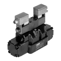
Directly operated and pilot operated directional control valves
Series D1VW / D1DW / D3W / D3DW / D31DW / D41VW / D81VW / D91VW
15
Translation from German
Parker Hannin Corporation
MSG11-5715-662 DCV UK.indd 21.07.22
The factory setting of the position control switch must not be changed.
Notes on installation
• Connections to the limit switch must be laid
separately from mains connections, for example
power supplies to motors or magnets, because
inductive voltage peaks would otherwise pass
via the supply network to the limit switch, which
could be damaged even though a protection
circuit is installed.
• A suitable DC power supply is required for the
switch. The ripple of the power supply must not
exceed 10 %.
• Voltage spikes occurring when inductive loads
are removed should be eliminated using a
suitable protection circuit, for example yback
diodes.
• A bui|t-in overload protection circuit suspends
the switching function of the limit switch if an
overload occurs. When the overload ends, the
limit switch automatically resumes operation.
• The limit switch must not be installed close to
AC consumers, e.g. AC solenoids, which may
cause disruption. A minimum distance of 0.1 m
must be observed in all cases.
• The product may only be operated in the condi-
tions set out in the technical data.
• Connections must follow the connection list.
16. Technical data
Position control switch
Supply voltage [VDC] 24
Tolerance supply voltage [%] ±20
Ripple supply voltage [%] ≤10
Polarity protection [V] 300
Current consumption without load [mA] ≤20
Switching hysteresis [mm] <0.06
Max. output current per
channel, ohmic [mA] 250
Ambient temperature [°C] -20 … +85
Protection IP65 acc. EN 60529
CE conform EN 61000-4-2/EN 61000-4-4/EN 61000-4-6
1)
/ENV 50140/ENV 50204
Min. distance to next AC solenoid [m] 0.1
Interface M12x1 to IEC 61076-2-101
1
1
0
0
0
[mm]
Stroke
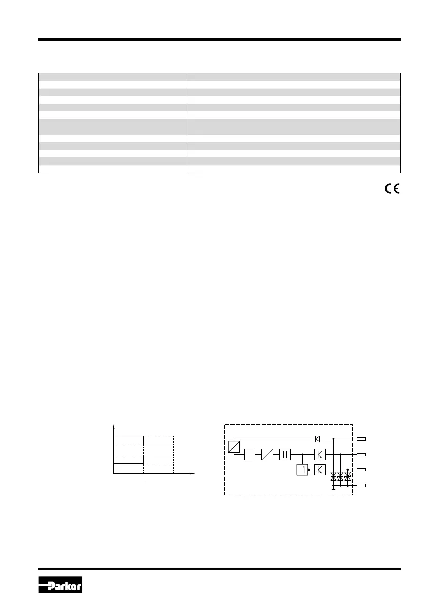
Pin 2
Pin 4
max. 1.8 V
min. -2.5 V
Voltage
Voltage U
B
-22
(-10)
2
3)
)
+22
2)
3)
(+40)
Connection diagramLimit switch
Type 118368-01
This switch is dedicated for the supervising of one trip point. When the trip point is reached, pin 4 is
non conducting, this means a normally closed function. Simultaneously pin 2 becomes conducting,
this means a normally open function.
U
Out
GND
Out neg.
S
1
4
2
3
DC st
DC
Osz.
DC
AC
1)
Only guaranted with screened cable and female connector
2)
Type 118368-01
3)
Type 118370-01

 Loading...