EasyManua.ls Logo

Parker GVM Series - Liquid Cooling Diagram

Parker GVM Series
82 pages
To Next Page IconTo Next Page
To Previous Page IconTo Previous Page
Loading...
- 62
18-06-08 PVD3668_GB_GVM_June_2018
3.6.6. Liquid cooling diagram
Recommendation: The use of a filter allows reducing the presence of
impurities or chips in the liquid circuit in order to prevent any obstruction.
This section shows typical liquid cooling diagram:
Any other cooling circuit system is fully under customer responsibility.
Chiller or Exchanger
Pump
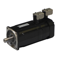
GVM motor
Recommendations:
- Check liquid flow at this point
- Check inlet temperature
There is no
recommendation
on liquid inlet and
outlet position
Recommendations:
- Check inlet temperature
Pump
GVM motors
Liquid flow
regulators
Liquid flow
meter
Liquid flow
meter
Chiller or Exchanger

Table of Contents

Related product manuals