- 70 –
18-06-08 PVD3668_GB_GVM_June_2018
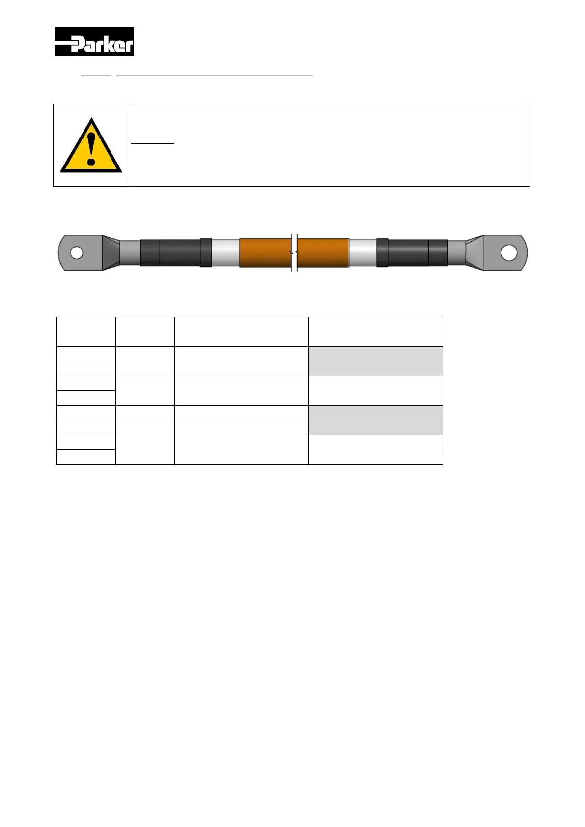
3.8.3. Mains supply connection diagrams
Parker can provide High Power cables, to be placed between the motor and the drive, with
standard lengths of 1, 2, 3 or 4 meters.
Depending on the rated motor current, indicated on the motor datasheet, 2 cable cross-
sections can be proposed as follows :
Depending on the required cable length (1, 2, 3 or 4m), the “x” letter of the part number
is to be replaced by 1, 2, 3 or 4.
The minimum bending radius is 4 times the cable diameter, for the CBM250 = 40 mm ; for
the CBM500 = 60 mm.
Please note that you can use the same type of cables between the drive and the battery
(modifying the terminal on the battery side)
Caution: A bad tightening on the cable or a too small cable section can
generate an overheating and damage the motor.
 Loading...