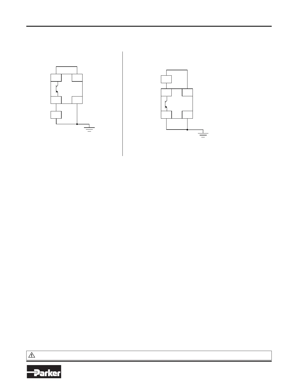
EExxaammpplleess ooff wwiirriinngg ttoo XX1111//0055 aanndd XX1111//0066.
Active high output: Active low output:
The load is energized and X11/05 is high
when STO is in the intended safe STO
state.
The load is energized and X11/06 is low
when STO is in the intended safe STO
state.
X11/06
X14/03
24VDC
X11/05 X14/04
890STO
LOAD
X11/06 X14/03
24VDC
X11/05 X14/04
890STO
LOAD
0V
0V
Hybrid Actuation System
Cylinders SSeerriieess HHAASS 550000
Catalog HY08-
SSaaffee TToorrqquuee OOffff
WWAARRNNIINNGG:: This product can expose you to chemicals including LLeeaadd aanndd LLeeaadd CCoommppoouunnddss which are known to the State of
PPRROOPP 6655 WWAARRNNIINNGG
California to cause cancer and birth defects or other reproductive harm. For more information go to www.P65Warnings.ca.gov
PPaarrkkeerr HHaannnniiffiinn CCoorrppoorraattiioonn
Cylinder Division
Des Plaines, Illinois
56
wwwwww..ppaarrkkeerr..ccoomm/
cylinder
•
The examples show the use of the 24V supply provided on X14/03 (+24V) and X14/04 (0V)
as source of power to a load. Alternatively an external 24V supply could be used.
Note: If a drive is powered from 24V only, i.e., 24V is applied to terminals X13/01 or X13/02
and the 3 phase power is off, the STO user output will still reflect the status of the two STO
user inputs.
SSTTOO TTeecchhnniiccaall SSppeecciiffiiccaattiioonn
IInnppuuttss SSppeecciiffiiccaattiioonn
STO A Input and STO B Input comply with IEC61131-2. Note: inputs do not have hysteresis.
Recommended input voltage for low level: 0V to +5V
Recommended input voltage for high level:
Typical input threshold voltage: Absolute
maximum input voltage: Typical input
current @ 24V Indeterminate input range:
Fault detection time
3
:
+21.6V to +26.4V
+10.5V
-30V to +30V
9mA
+5V to +15V. Function is undefined.
2.3sec typical;
< 1.6sec will not generate a fault
> 3.0sec will generate a
fault.

 Loading...


