(6) Sheet type
(7) - Sheet part no. and index
(8) - Product(s) affected
(9) - Page no. of the sheet
Sheet index:
Tool recommended for maintenance ....................................... A 00 - page 99
Access to internal components ................................................... A 10 - page 102
Fuse replacement ..................................................................... A 20 - page 103
Electric circuit operating cycle and testing ............................. A 30 - page 104
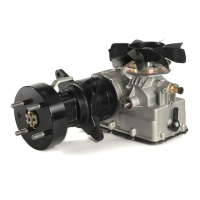
Motor replacement .................................................................... A 40 - page 105
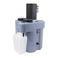
Maintenance of flaring pin lubricating system ....................... A 50 - page 106
Hydraulic circuit checks ......................................................... A 60 - page 107
Cam setting (clamping of the tube to be flared) ...................... A 70 - page 110
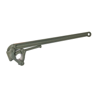
Tool recommended for maintenance
Tool icons
The icons in the header of the
maintenance sheet state the tool
required for each type of work.
Each icon represents an image of the
tool type and its size.
Allen key
e.g. 4 mm Allen key
Socket wrench
e.g. 7 mm socket wrench
Internal circlip pliers
Ampere meter
 Loading...