PAGE 14
FIGURE 2-6
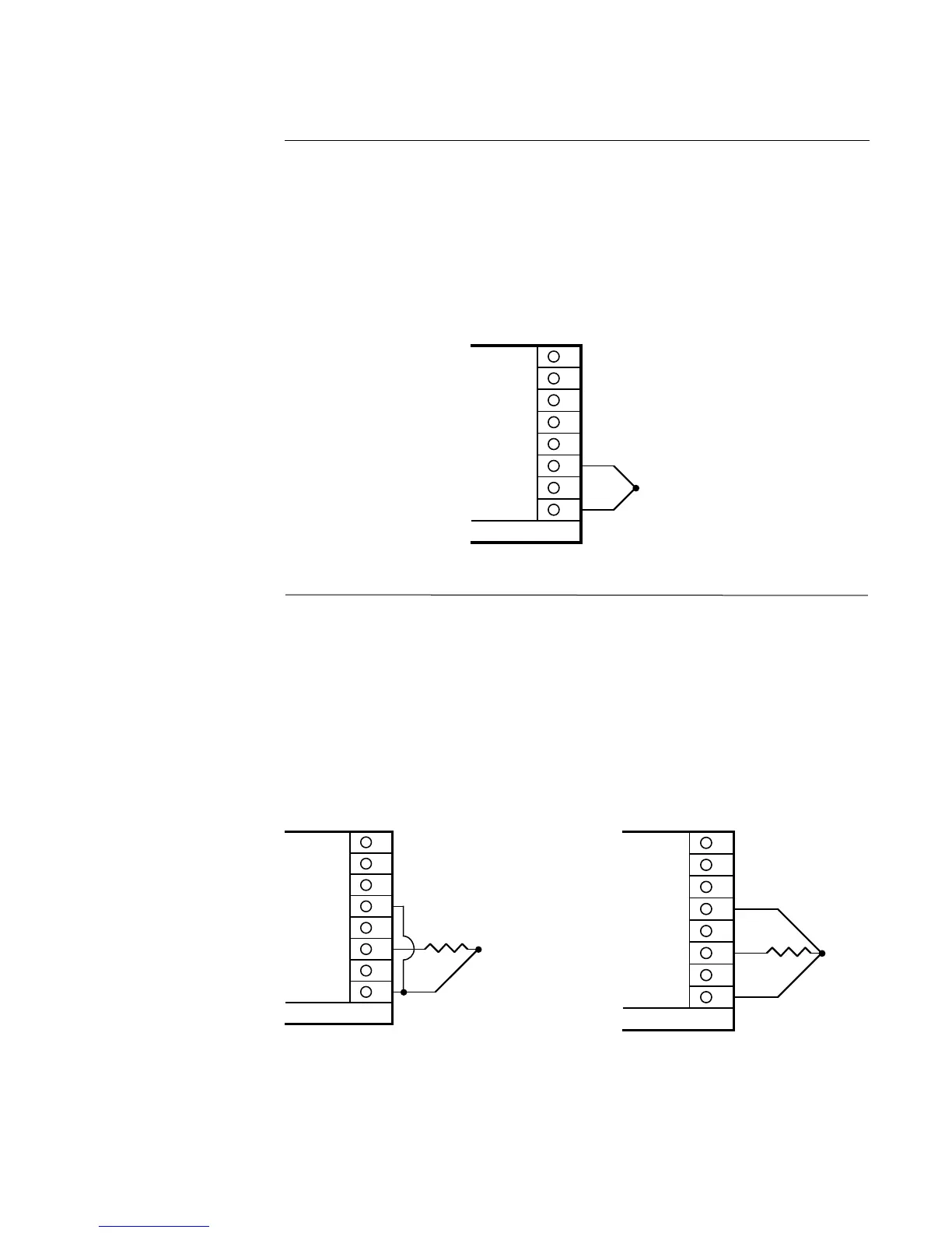
Thermocouple (T/C) Input
Make thermocouple connections as illustrated below. Connect the positive leg of the thermo-
couple to terminal 3, and the negative to terminal 1. For industrial environments with com-
paratively high electrical noise levels, shielded thermocouples and extension wire are recom-
mended. Be sure that the input conditioning jumpers are properly positioned for a thermo-
couple input. See Appendix A-2 (page 60) and A-3 (page 61, 62).
FIGURE 2-7
RTD Input
Make RTD connections as illustrated below. For a three wire RTD, connect the resistive leg
of the RTD to terminal 3, and the common legs to terminal 1 and 5. For a two wire RTD,
connect one wire to terminal 1 and the other wire to terminal 3 as shown below. A jumper
wire supplied by the customer must be installed between terminals 1 and 5. Be sure that the
input conditioning jumpers are properly positioned for an RTD input. See Appendix A-2 (page
60) and A-3 (page 61, 62).
8
7
6
5
4
3
2
1
THERMOCOUPLE INPUT
+
-
300 OHMS
MAXIMUM
LEAD
Rear view
8
7
6
5
4
3
2
1
2 WIRE RTD INPUT
100 OHM*
PLATINUM
JUMPER*
Rear View
*Supplied by customer
100 OHM*
PLATINUM
8
7
6
5
4
3
2
1
3 WIRE RTD INPUT
Rear View
*Supplied by the customer