PAGE 21
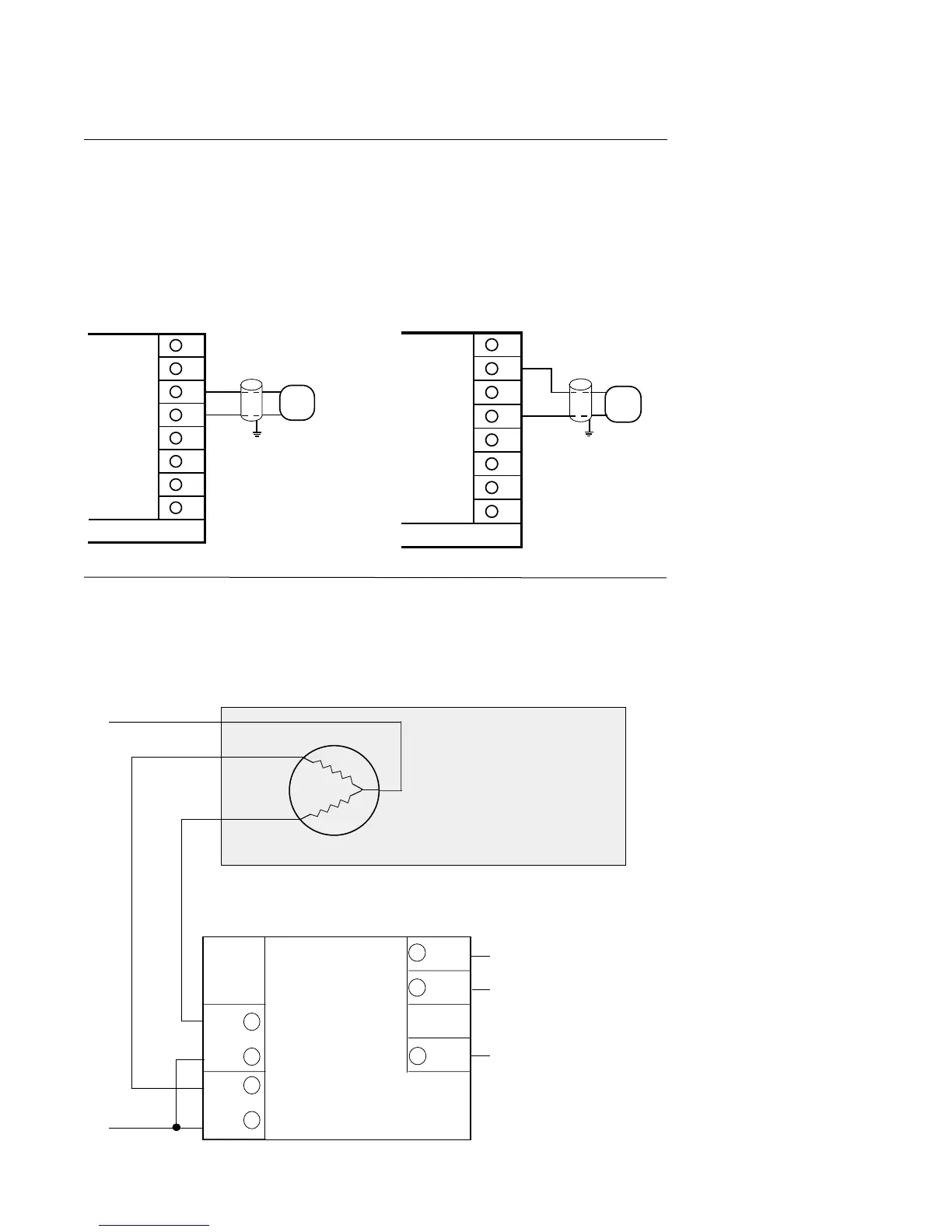
FIGURE 2-14
mADC Output
Connections are made for current outputs 1 or 2 as shown below. Connect the positive lead
to terminal 6 for Output 1 or terminal 7 for Output 2 , the negative leads connect to terminal 5.
Current outputs will operate up to 650 ohms maximum load. The current output(s) are
4 - 20 mADC. With the EA option, they can be selected for either 4-20 or 0-20 mADC.
FIGURE 2-15
Position Proportioning Output
The relay and slidewire feedback connections are made as illustrated below. The relay
assigned to Output 1 will be used to drive the motor in the open direction and the relay
assigned to Output 2 will be used to drive the motor in the closed direction. The minimum
slidewire feedback resistance is 135 ohms, the maximum resistance is 10K ohms.
D
C
RELAY A
5
8
7
E
F
RETURN
+
POS.PROP.
WIPER
POS.PROP.
HIGH
RELAY B
Modulating Motor
L1
L2
Rear View
OPEN
CLOSE
8
7
6
5
4
3
2
1
DC CURRENT OUTPUT 1
+
-
LOAD
650 OHMS
MAXIMUM
Rear View
Shielded
Twisted
Pair
8
7
6
5
4
3
2
1
DC CURRENT OUTPUT 2
+
-
LOAD
650 OHMS
MAXIMUM
Rear View
Shielded
Twisted
Pair