PAGE 18
FIGURE 2-11
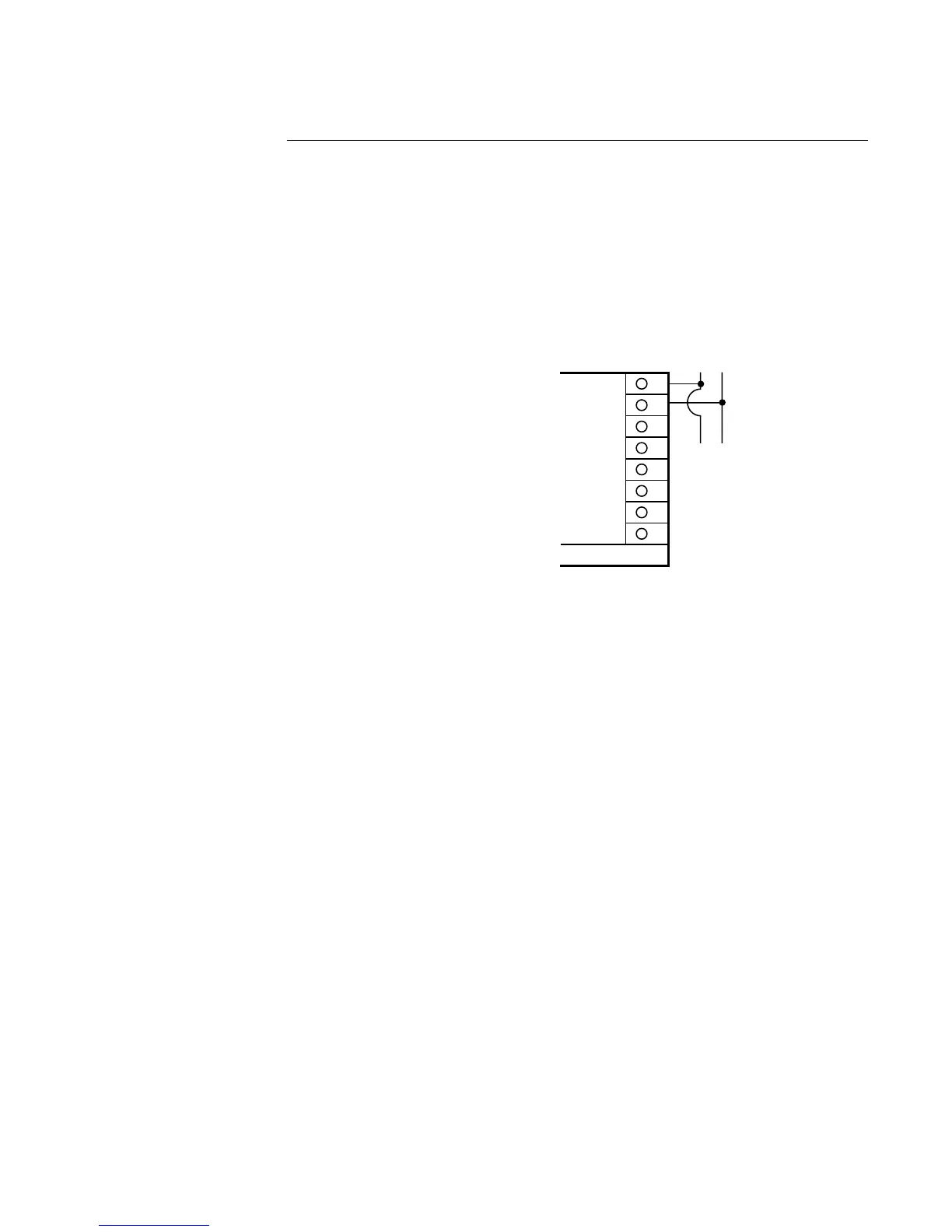
Remote Digital Communications RS 485 Terminals 7 & 8
If the communications network continues on to other units, connect the shields together, but
not to the instrument. A terminating resistor should be installed at the terminals of the last
instrument in the loop. The shield should be grounded at the computer or the
convertor box, if used. See the Protocol Manual (Form 2878) for more details on the use of
the digital communications option.
8
7
6
5
4
3
2
1
Output 2 cannot be DC Current
FROM HOST
COMPUTER
TO OTHER
INSTRUMENTS
DIGITAL COMMUNICATIONS
CONNECTIONS - TERMINALS 7 & 8