PAGE 15
FIGURE 2-8
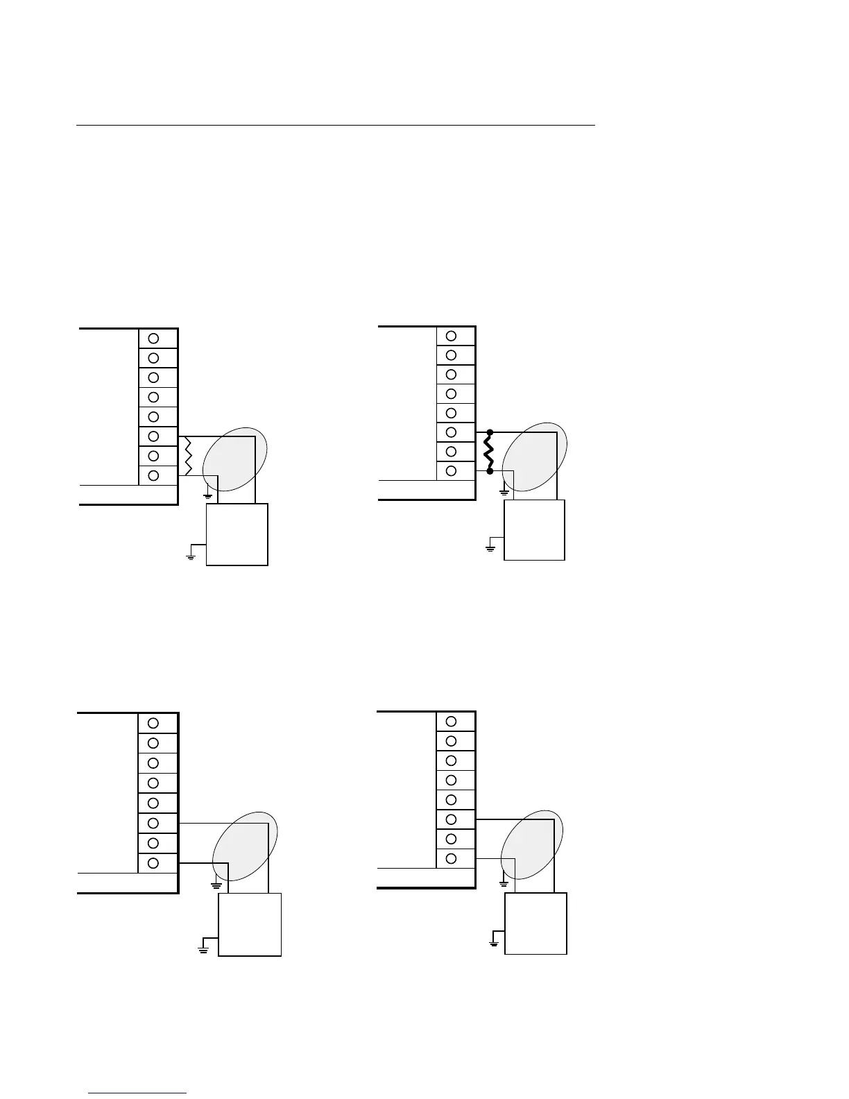
Volt, mV, mADC Input
Make volt, millivolt and milliamp connections as shown below. Terminal 3 is positive and
terminal 1 is negative. Milliamp input requires a 250 ohm shunt resistor (supplied with the
instrument) installed across the input terminals and by configuring the instrument for either 0
to 5 or 1 to 5 VDC input. If desired, milliamp DC input can be facilitated by installing an
optional 2.5 ohm resistor across the input terminals and configuring the instrument for either 0
to 50 or 10 to 50 mVDC. Be sure that the input conditioning jumpers are properly positioned
for the input type selected. See Appendix A-2 (page 60) and A-3 (page 61, 62).
NOTE: Fault detection is not functional for 0-20mA inputs.
NOTE: Fault detection is not functional for 0-20mA inputs.
8
7
6
5
4
3
2
1
MILLIAMP DC INPUT
+
-
MILLIAMP DC
SOURCE
2.5 OHM SHUNT
RESISTER
REQUIRED
Rear View
Shielded Twisted
Pair
8
7
6
5
4
3
2
1
MILLIAMP DC INPUT
+
-
MILLIAMP DC
SOURCE
250 OHM SHUNT
RESISTER
REQUIRED
Rear View
Shielded Twisted
Pair
8
7
6
5
4
3
2
1
MILLIVOLT DC INPUT
+
-
MILLIVOLT DC
SOURCE
50 MILLIVOLT DC
MAXIMUM
Rear View
Shielded Twisted
Pair
8
7
6
5
4
3
2
1
VOLT DC INPUT
+
-
VOLT DC
SOURCE
5 VOLT DC
MAXIMUM
Rear View
Shielded Twisted
Pair