PAGE 16
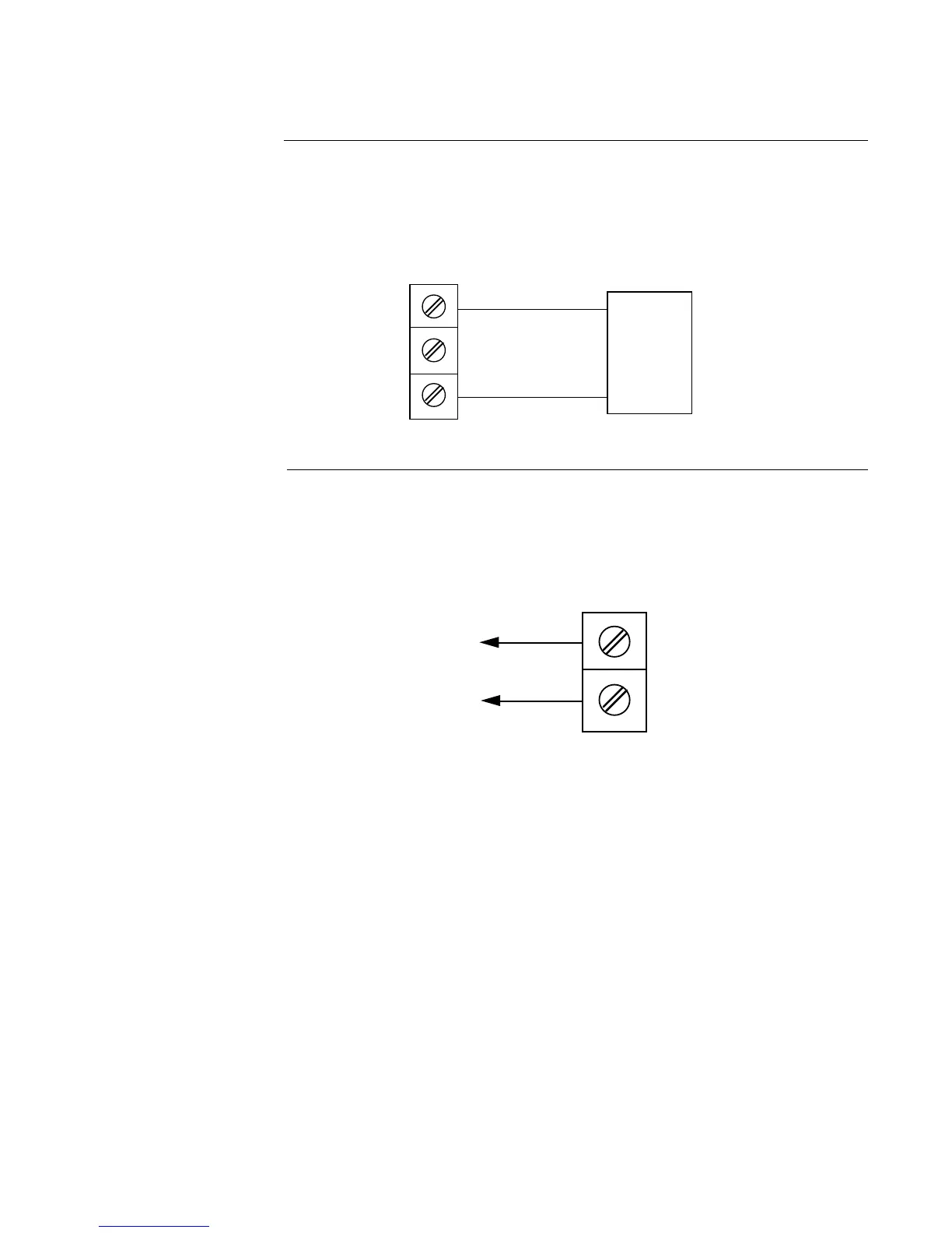
FIGURE 2-9A
24 Volt Transmitter Power Supply (XP Option)
Make connections as shown below. Terminal 3 is positive (+) and terminal 1 is negative (-)/
Be sure the input conditioning jumpers are properly positioned for the input type selected.
See Figure A-2 Processor Board, page 60, and Figure A-3 Option Board, page 61 or 62. Note
the 250 ohm shunt resistor is not required.
FIGURE 2-9B
24 Volt Power Supply (XA Option)
Make connections as shown below. Terminal G is positive (+) and terminal H is negative (-).
Be sure the input conditioning jumpers are properly positioned. See Figure A-2 Processor
Board, page 60 and Figure A-3 Option Board, page 61 or 62.
+3
2
-1
+
-
Two Wire
Transmitter
H -
G +
24VDC