LIST OF FIGURES
Figure 1.1 Unpacking the machine ......................................................... 1
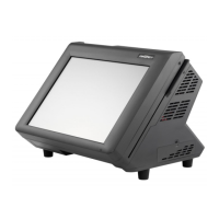
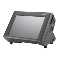
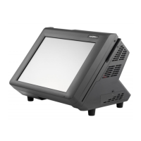
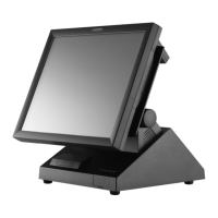
Figure 1.2 Front-right view ...................................................................... 2
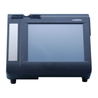
Figure 1.3 Rear view ............................................................................... 3
Figure 1.4 PT-6212 I/O connectors ......................................................... 4
Figure 2.1 Main BIOS menu.................................................................... 6
Figure 2.2 Standard CMOS Features menu ........................................... 8
Figure 2.3 IDE Primary Master submenu ................................................ 9
Figure 2.4 Advanced BIOS Features menu .......................................... 10
Figure 2.5 CPU Feature submenu ........................................................ 12
Figure 2.6 Hard Disk Boot Priority menu............................................... 13
Figure 2.7 Advanced Chipset Features menu ....................................... 14
Figure 2.8 Integrated Peripherals menu................................................ 16
Figure 2.9 OnChip IDE Device submenu .............................................. 17
Figure 2.10 Onboard Device submenu ................................................. 19
Figure 2.11 SuperIO Device submenu .................................................. 20
Figure 2.12 Power Management Setup menu ...................................... 21
Figure 2.13 PnP/PCI Conguration menu ............................................. 23
Figure 2.14 IRQ Resources submenu................................................... 24
Figure 2.15 PC Health Status menu ..................................................... 25
Figure 2.16 Frequency/Voltage Control menu ...................................... 26
Figure 4.1 Connecting a cash drawer ................................................... 44
Figure 4.2 PT-6212 mainboard jumpers................................................ 48
Figure 4.3 PT-6212 mainboard connectors ........................................... 49
Figure 4.4 Inverter connectors .............................................................. 50
Figure 6.1 Exploded diagram main parts .............................................. 61
Figure 6.2 Exploded diagram printer parts ............................................ 62