Microdrive Series Instruction Manual
4201-109 Rev I
14
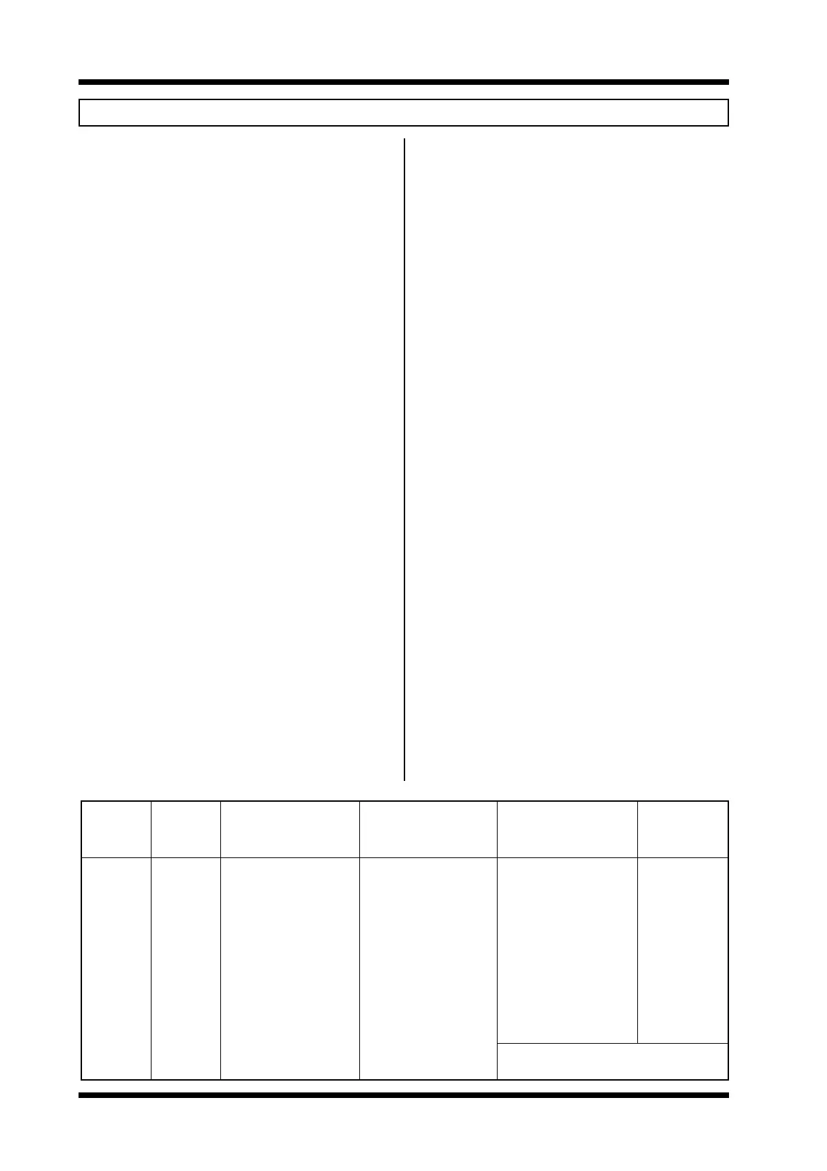
MICRODRIVE-i (UDi) SPECIFICATIONS
OUTPUT OUTPUT kVA OUTPUT POWER DIMENSIONS NETT
MODEL CURRENT 380Vac 415Vac440Vac 380Vac415Vac440Vac H W D WEIGHT
Amps kVA kVA kVA kW kW kW mm mm mm kg
UDi90 90 59.2 64.7 68.6 45 51 55 1350 405 422 126
UDi110 110 72.4 79.1 83.8 55 59 63 1350 405 422 126
UDi140 140 92.1 101 107 75 80 80 1350 405 422 126
UDi170 170 112 122 130 90 90 100 1350 545 422 160
UDi205 205 135 147 156 110 110 110 1350 545 422 175
UDi250 250 165 180 190 132 140 150 1350 545 422 175
UDi300 300 198 216 229 160 170 185 1350 965 422 303
UDi340 340 224 244 259 180 200 200 1350 965 422 303
UDi480 480 316 345 366 257 280 300 1350 965 422 333
UDi660 660 434 474 503 355 400 425 1350 1385 422 456
UDi830P 830 547 598 634 445 485 520 Consists of two UDi480
UDi1140P 1140 752 821 871 614 693 736 Consists of two UDi660
INPUT
Input supply voltage 380440Vac
Input supply tolerance -20% to +10%
Phase 3 phase, 3 wire,
earthed neutral supply
Input frequency range 4862 Hz
Power factor (fundamental) .95
Input current < output current
Power loss ride through > 2 seconds
May also be operated from 450700Vdc or 380440Vac
single phase supply - refer to Appendix 5.
OUTPUT
Current overload capability 150% for 30 seconds
Efficiency (full load, 50Hz) >97%
Power on delay <1 sec
Suit motor rated voltages 10995Vac
Suit motor rated frequencies 10250 Hz
Output voltage - cannot be greater than input voltage
Voltage regulation <±3%
Frequency range 0 to ±200Hz
Frequency resolution 0.01Hz
Control method Space vector modulation
Carrier frequency 2kHz (4kHz selectable)
Dominant ripple frequency 4kHz (8kHz selectable)
Tacho speed regulation 0.01%
ENVIRONMENTAL
Protection standard:
Cabinet Dust and water splash
protected; Pollution degree 3
Baseplate IP00; Pollution degree 2
Operating temperature 050°C
Storage temperature -40°C to +80°C
Relative humidity <90%, noncondensing
Altitude 1000m
Altitude derating (>1000m) -1% per 100m; 3000m max
UDi PROTECTION
Supply loss Input phase loss
Output current limit IGBT overload
Short circuited load Ground fault
Low DC bus voltage Regeneration limit
Excessive DC bus voltage Motor over temperature
UDi thermal model Control PCB failure
Dynamic brake thermal model Serial comms loss detection
MOTOR PROTECTION
Stall avoidance Stall protection
PTC thermistor input Phase current imbalance
Shear pin mode Combined overload alarm
Thermal model overtemperature trip
FREQUENCY CONTROL SOURCES
010Vdc 420mA
Greater of 010Vdc or 420mA
Keyboard Inch 1, Inch 2
Process follow Process control
Switch control - continuous Switch control - 7 preset
Motorised potentiometer RS232/RS485 (Options)
CONFIGURABLE SWITCH CONTROLS
Stop Start
Start/reset Stop/reset
Inch Inch latched
Direction invert Emergency stop
Latched start with direction Crane functions
RS232/RS485 control input (Options)
CONFIGURABLE RELAY OUTPUTS
3 relays; 230Vac/30Vdc/1A
1 x change over; 2 x normally open
Output selection:
Failsafe fault UDi started
UDi running UDi started or running
UDi overloaded Motor overloaded
Frequency sense point Current sense point
Direction At set frequency
Combined overload alarm Feedback sense
Power flow direction RS232/485 controlled
(Options)
CONFIGURABLE 010V ANALOGUE OUTPUT
Output selection:
0100Hz 0150% UDi current
0200Hz 0500Vac output voltage
010V RS232/RS485 (Options)
0150% UDi torque component of current
0150% motor power
DIGITAL FREQUENCY OUTPUT
26.25 times the UDi output frequency
CURRENT LIMIT SOURCES
010Vdc 420mA
Keyboard