Microdrive Series Instruction Manual
4201-109 Rev I
57
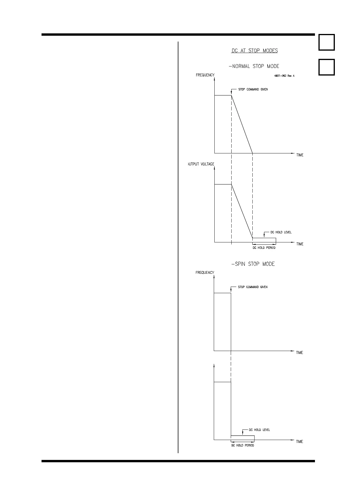
26, 27 DC STOPPING CONTROLS
Screen 26 DC LEVEL =0%
Description DC (0Hz) HOLD/BRAKE VOLTAGE AT STOP
Min/Max 0/25
Units %V(MOTOR)
Screen 27 DC TIME =0.0s
Description PERIOD OF DC HOLD VOLTAGE AT STOP
Min/Max 0.0/25.0
Units SECS
FUNCTION DC level sets the amount of DC voltage (hence
current) applied to the motor when the
Microdrive frequency reaches zero when
stopping. When applied, the DC current causes
the motor to resist movement and is used to
brake the motor.
DC Time sets the period of application of the DC
level after the Microdrive has reached zero
frequency, upon receiving a stop command.
Using DC at stop together with the spin stop
mode (Screen 61) can be useful in positioning
control systems.
Notes: To achieve DC holding while the control
frequency is at zero, but the Microdrive is not
stopped, use the boost voltage (Screen 14).
SETTING UP If motor braking upon stopping is not required,
leave both settings to zero (factory set values).
If braking at stop is required, set the DC time to
a suitable value (e.g., 2 seconds). While
repeatedly stopping the motor, adjust the DC
level to provide the desired braking force
(typically achieved when the motor current
equals its rated current). You must be careful
that you do not overheat the motor by operating
for too long at zero frequency, with too much
DC level, or without adequate cooling. Be
careful not to set the DC level so high that it
causes the Microdrive to current limit (status
display - ILT).
26
27