Microdrive Series Instruction Manual
4201-109 Rev I
89
79 MULTI-FUNCTION INPUT INVERSION
Screen 79 MFI INVERT =N
Description MULTI-FUNCTION INPUT LOGICAL INVERSION
Range [Y]ES/[N]O
Default Value [N]O
Stop to ChangeYES
FUNCTION The Microdive has the ability to have its input
circuits operated in two modes:
STANDARD (79 Not Inverted) - Pull low to
activate
INVERTED (79 Inverted) - Pull high to
activate
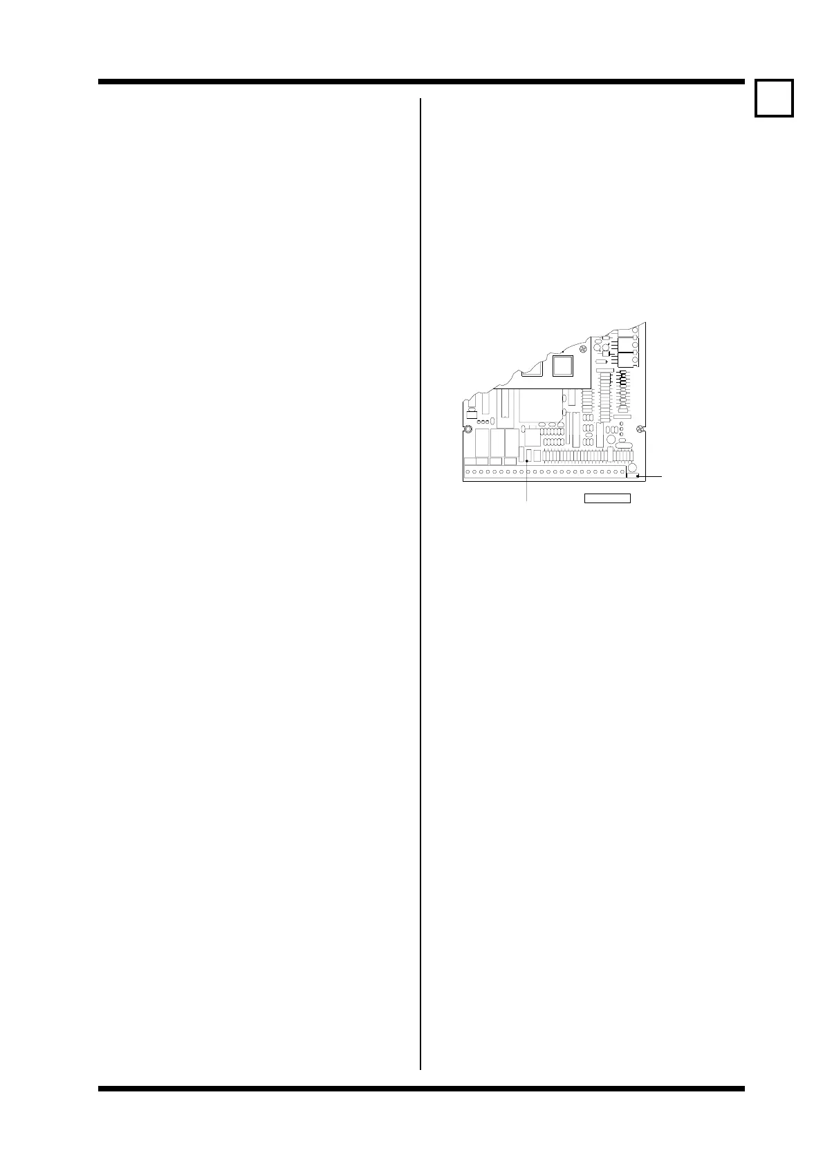
Link J1 controls the internal pull up or down on
each input (See fig. 2.2)
All descriptions in this manual assume the
default (active low) configuration. The inverted
configuration is provided as this configuration
is also common, and is a requirement of some
standards.
SETTING UP Determine whether your application requires
pull low to activate logic or pull high to activate
logic.
If PULL HIGH TO ACTIVATE is required you
must make two adjustments:
WARNING 1 Ensure the motor is disconnected. The
Microdrive must have its multi-function input
mode select set to commission mode when
making this adjustment.
SELECTING ACTIVE HIGH LOGIC:
i) Select multi-function input mode
(Screen 66) to disable inputs -
66 I/P MODE = 00 COMMISSION
ii) Shift Link J1 on the control PCB to the
"2" position.
iii) Set Screen 79 to [Y]ES to invert all
input logic -
79 MFI INVERT = Y
iv) Select the desired multi-function input
mode (Screen 66).
WARNING 2 It is strongly recommended that ALL
Microdrives on any one site should be
configured for either active pull low or active
pull high to minimise the risk of non fail-safe
operation if drives are exchanged.
Note: Inverting the input levels does not affect the
function of the input - it simply inverts the
active and inactive states.
The Microdrive must have its multi-function
input mode select (Screen 66) set to
commission mode when making this adjustment.
The warning message ILLEGAL ACCESS
will be displayed if the Microdrive does not
have Screen 66 set to
66 I/P MODE = 00 COMMISSION.
The setting of the multi-function input invert
screen is not modified when the Microdrive is
initialised from Screen 98. This is to provide
extra protection against accidental starting of
the Microdrive.
P4
2 − BIAS LOW
1 − BIAS HIGH
BIAS LINK J1
INPUT LOGIC
J1
J2
4807−292 Rev C
4−20mA
+15V
0−10V
CHASSIS EARTH
E − EARTH TO CHASSIS
X − FLOATING
LINK (J2)
79