Microdrive Series Instruction Manual
4201-109 Rev I
100
Adjustment 24 FR F2
(Default) (=+60.0Hz)
Setting 60.0
Notes Set equal to MAX FR.
Adjustment 43 T GAIN
(Default) (=20.0)
Setting 2.0
Notes Calculated according to instructions in the
detailed description of Screen 43:
Encoder frequency at 50Hz = 1500 (rpm) x 1000 (ppr)
60 (secs)
= 25 kHz
Tacho gain = 50 (Hz)
25 (kHz)
= 2.0 (Hz/kHz)
MODES
Mode 64 REF FR
(Default) (= 010V)
Setting 420mA
Notes Selects 420mA as the reference source.
Mode 65 FB SRC
(Default) (=O/LOOP)
Setting TACHO
Notes Selects tacho feedback mode.
Mode 66 I/P MODE
(Default) (=01)
Setting 01
Notes Sets the multi-function inputs up for three wire
control.
1000PPR
14MOTOR PTCMOTOR PTC
MODE = 1
4807−076 Rev E
SWITCH INPUT 2
SWITCH INPUT 1
0V
SWITCH INPUT 5
SWITCH INPUT 4
SWITCH INPUT 3
START
STOP
8
9
EMERGENCY STOP
DIRECTION INVERT
STOP/RESET
0V
12
11
10
13
EXAMPLE: TACHO CONTROL
WIRING CONFIGURATION
+10V POTENTIOMETER
0V
TACHO INPUT
TACHO SUPPLY
0V
FREQUENCY OUTPUT
FREQUENCY INPUT
0V
FREQUENCY INPUT
0−10V ANALOGUE O/P
I/O NAME
PDL ENCODER 0300−EN
19
SUPPLY
TACHO INPUT
+12V/50mA MAX
0V
0V
15
16
18
17
0V/−mA
0−10V
+ 4−20mA
F = 26.25 F
21
20
O/P
22
23
+V
0V
A
SOURCE
0−10V=0−100Hz
FUNCTION
24
4−20mA
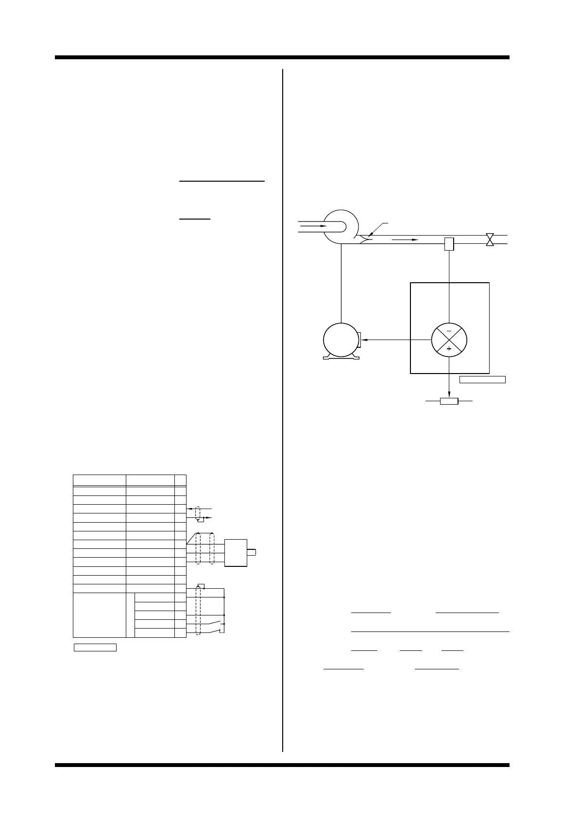
4C: APPLICATION EXAMPLE -
CONSTANT PRESSURE PUMPING
Constant pressure pumping is a common application of AC
Motor Speed Controllers. This appendix shows the
configuration, wiring and adjustment of a typical example.
Constant pressure pumping systems maintain the pressure of
the outgoing pipe by controlling the speed of the pump. If the
demand increases (e.g., opening a tap) the pressure de-
creases and the pump has to wind up the speed. The system
pressure is used as a feedback signal. The output pressure is
selected with the setpoint potentiometer.
M
4807−247 Rev D
DRIVE
SET PRESSURE
PRESSURE
SENSOR
FEEDBACK
NON−RETURN VALVE
TAP
The example given is of a system of the following specification:
Control signal 010V (potentiometer)
Pressure sensor 420mA, 100psi,
12V supply, 3 wire
Motor 132 kW, 245A,380V,
1485 rpm
Microdrive model 250
Stop/start control 2 wire
Direction control reverse inhibited
The configuration table (not including irrelevant and/or settings
which have not been altered from factory set values) and
wiring configurations follow:
CONSTANT PRESSURE PUMPING EXAMPLE
CONFIGURATION TABLE
DRIVE NO: _________ MODEL:____UDi-250____
SITUATION: __Constant Pressure Pump_______________
MOTOR kW: _132__ A:_245_ V:_380_
POLES:____4____ RPM:__1485____