Reference Page. . .
To configure the controller(s), they must be connected to the Pelican wireless network and the network must have a
Pelican gateway to connect everything to the Internet.
Before start-up, verify the following are installed and wired to the thermostat:
Damper Control –
The controller is wired to open, close,
and/or modulate the zone damper.
Discharge Temperature Sensor –
The controller is wired to a 10K Type 2
thermistor installed after the damper
and reheat. Is reading accurate
temperatures.
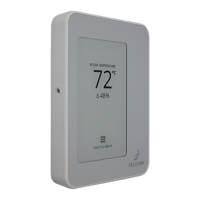
Pelican thermostat –
The thermostat is properly mounted
in the room to read accurate zone
space temperature, humidity, and
CO2 levels; as required for your
application. Follow the installation
guide provided with the thermostat
for specific thermostat mounting and
installation instructions.
Reheat Control (as required) –
The controller is wired to open, close,
and/or modulate the zone reheat.
Required. . .
Before Start-up
Provides. . .
◦ Provide or restrict air into zone.
◦ Airflow management.
◦ Historical Data Log.
Mech Diagrams: 7 – 12
Wiring Diagrams: 19 – 24
Configurations: 35 – 39
Sequences: 40 – 46
Mech Diagrams: 7 – 12
Wiring Diagrams: 25 – 28
Configurations: 35 – 39
Sequences: 40 – 46
Mech Diagrams: 7 – 12
Wiring Diagrams: 19 – 30
Configurations: 35 – 39
Sequences: 40 – 46
Mech Diagrams: 7 – 12
Wiring Diagram: 14
Configurations: 35 – 39
Sequences: 40 – 46
◦ Proof of damper operation.
◦ Reheat modulating reset (as
required).
◦ Historical Data Log.
◦ Room temperature.
◦ Set-point control.
◦ Logic to accessories controlling
dampers, reheats, terminal
fans.
◦ Demand Ventilation (as
required)
◦ Humidity management.
◦ Historical Data Log.
◦ Reheat discharge air into zone.
◦ Proof of reheat active.
◦ Historical Data Log.
Start-Up: Attached Thermostat Display to Back Plate
Before attaching the display, write down the serial
number displayed on the screen. This number will be
needed when configuring the thermostat.
Align the display with the back plate’s alignment pins,
then press it into the back plate until it clicks into place.
Turn on the power to the HVAC equipment connected to
the thermostat.
If your Pelican thermostat does not power on, refer to
page 33 for troubleshooting.
For instructions on configuring the thermostat,
reference “Start-Up - Setting Configurations” on page 35.
there are three (3) alignment
pins found on the left and right
sides of the base plate.
32

 Loading...