www.pelprostoves.com 7083-171H • February 23, 2015 35
increase distance from appliance if needed.
13. Snap Disc (Back Burn Protector) 200°F
Snap disc is mounted on the back of the auger tube in the center
of the appliance and has a reset button. There are two grey wires
connected to it. To access it remove the right side panel. If the fi re
tries to burn back into the feed system or push exhaust up the feed
tube, this snap disc will shut the entire system off. Unplug the stove
prior to resetting.
14. Vacuum Switch
The vacuum switch is located on the lower right side of the appliance
behind right side panel. There are two red wires attached to it. This
switch turns the feed system on when vacuum is present in the
fi rebox. The vacuum switch is a safety device to shut off the feed
motor if the exhaust or the heat exchanger system is dirty or plugged
or if the fi rebox door is open or exhaust blower failure.
15. Outside air inlet
The outside air tube can be attached to the 2” OD inlet tube on
the rear of the appliance.
When describing the location of a component,
it is always AS YOU FACE THE FRONT OF THE
APPLIANCE.
1. Control Board
The control board is located on the right side of the appliance
behind the lower right side panel.
2. Convection Blower
The convection blower is mounted in the rear of the unit. It pushes
air up the rear of the fi rebox, across the top and out the front. As
the air moves past the fi rebox it is heated.
3. Exhaust Blower
The exhaust blower is mounted on the left side of the appliance. The
exhaust blower is designed to pull the exhaust from the appliance
and push it out through the venting system.
4. Feed System
The feed system can be accessed in two areas. To access the
auger spring, remove the cove
r in the hopper.
To remove the
feed motor: Remove the right side panel and pull cotter pin that
connects motor to auger shaft.
5. Firepot
The fi repot is made of a combination of stainless steel and heavy
duty cold rolled steel. It is removable to aid in cleaning.
6. Fuse
The fuse is located on the control board. The fuse will blow should
a short occur and shut off power to the appliance.
7. Dial Control
The dial control is attached to the right side of the appliance. The
large dial controls the heat output where as the small dial below the
large dial is the trim feature. The LED blinks according to the state
of the appliance.
8. Hopper Switch
The hopper switch is located in the upper right hand corner of
the hopper. This switch is designed to shut down the feed motor
whenever the hopper lid is opened.
9. Igniter
The igniter is mounted in the chamber in the rear of the fi rebox below
the convection blower. Combustion air travels over the red hot igniter
creating super heated air that ignites the pellets.
10. Power Supply
The power cord connector in the rear of the unit. Check the wall
receptacle for 120 volt, 60 Hz (standard current). Make sure the
outlet is grounded and has the correct polarity. A good surge
protector is recommended.
11. Exhaust Probe
The exhaust probe is mounted to the side of the exhaust outlet in
the rear of the unit. It senses the temperature of the exhaust and
allows the control system to make decisions.
12. Ambient Probe
The ambient probe is located in the back panel. It has extra wire to
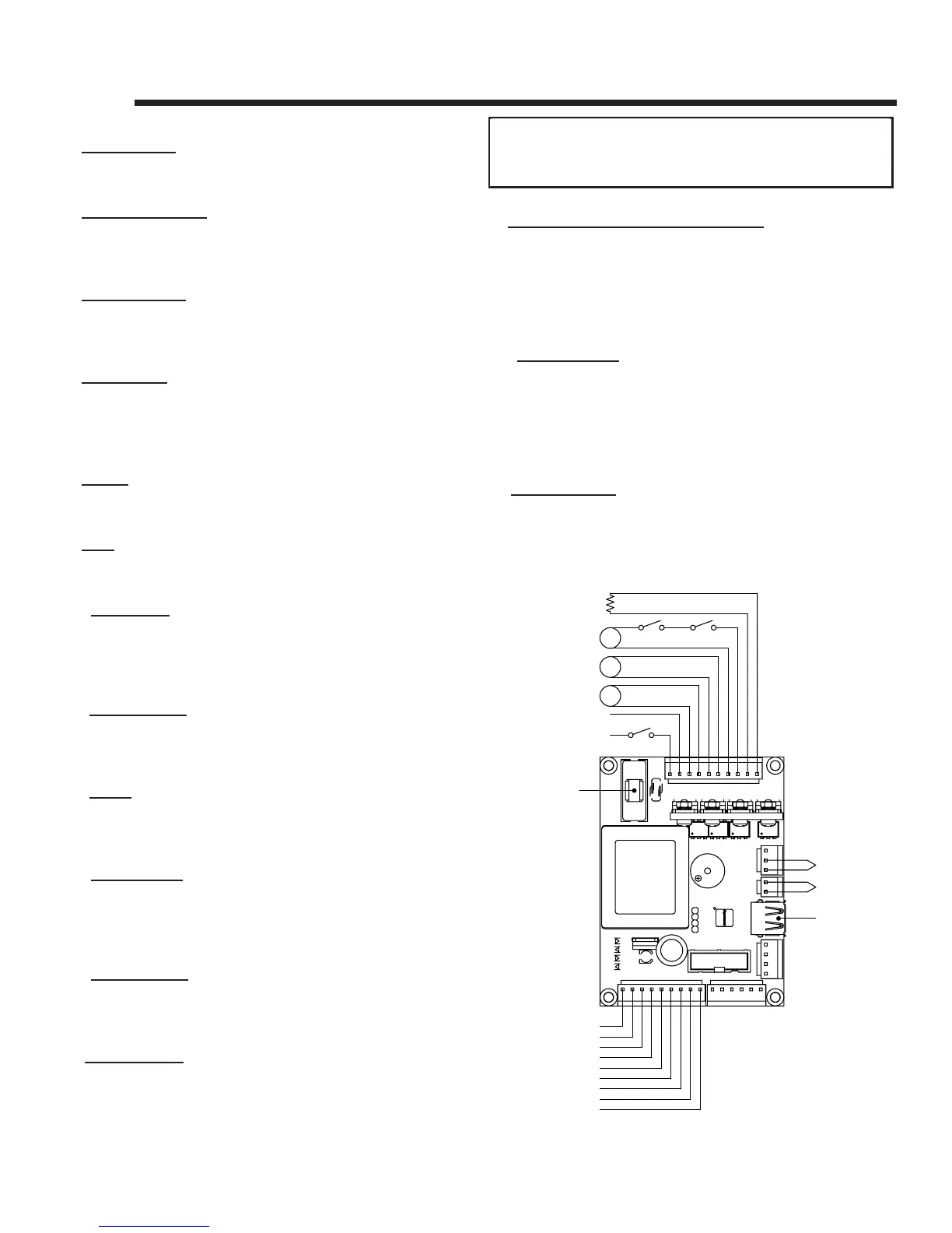
A. Component Function
M
M
M
110 V
LINE
NEUTRAL
IGNITER
FEED MOTOR
EXHAUST
BLOWER
CONVECTION
BLOWER
VACUUM
SWITCH
HOPPER
SWITCH
AMBIENT
TEMPERATURE
EXHAUST
TEMPERATURE
SERIAL PORT
(SERVICE ONLY)
BLACK
WHITE
PURPLE
PURPLE
BLUE
BLUE
RED
RED
BLACK
BLACK
POT SET TEMP VCC
POT SET TEMP GND
POT SET TEMP SIG
POT FEED ADJUST VCC
POT FEED ADJUST GND
POT FEED ADJUTS SIG
LED RED
LED AMBER
LED GREEN
FUSE
SNAP
DISC
B. Wiring Diagram
13 Reference Materials